Parallel plate transmission line with a concrete material slab
The present example considers a parallel plate transmission line with a concrete material slab.
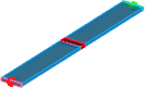
Parallel plate transmission line with a concrete material slab.
Parallel plate transmission line with a concrete material slab - violet colour on the both sides indicates PMC boundary conditions.
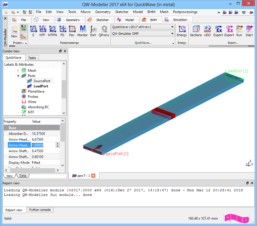
Parallel plate transmission line with a concrete material slab project in QW-Modeller.
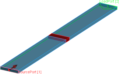
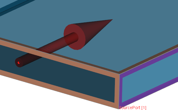
Simulation model presents parallel plate transmission line excited with a plane wave (red transmission line port) and terminated with a load port (green transmission line port) matched to the line. The transmission line is filled with air. A concrete slab of 7.5 mm thickness, made of material with relative permittivity equal to 4 is placed in the middle of the line.
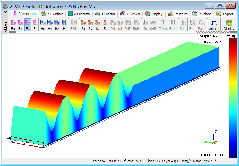
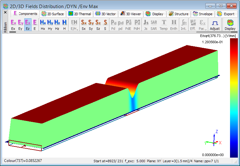
Distribution of time-maximum envelope of Ez field component at 5GHz.
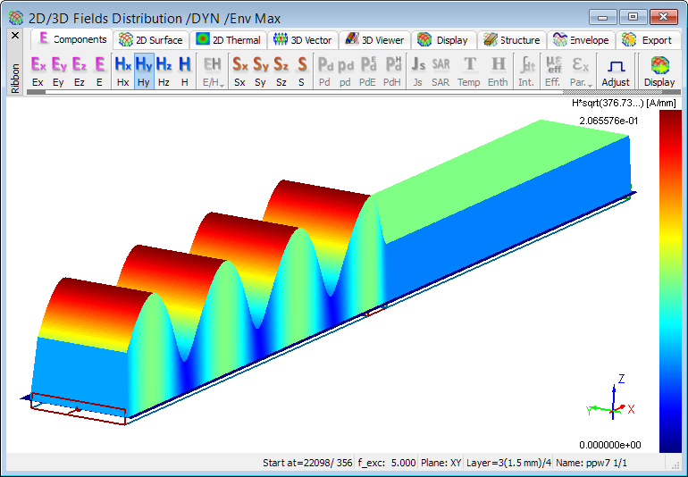
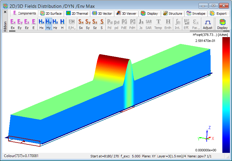
Distribution of time-maximum envelope of Hy field component at 5GHz.
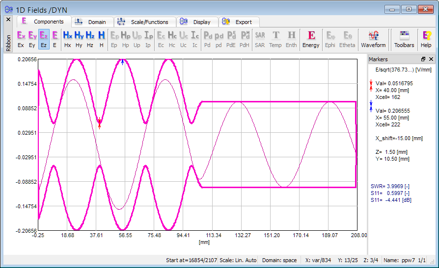
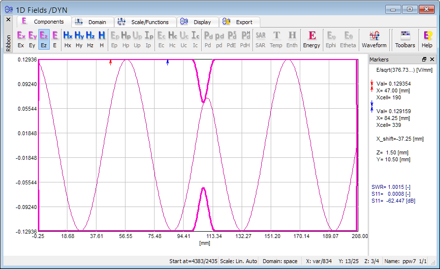
1D view of Ez field component distribution at 5GHz (instantaneous and envelope values).
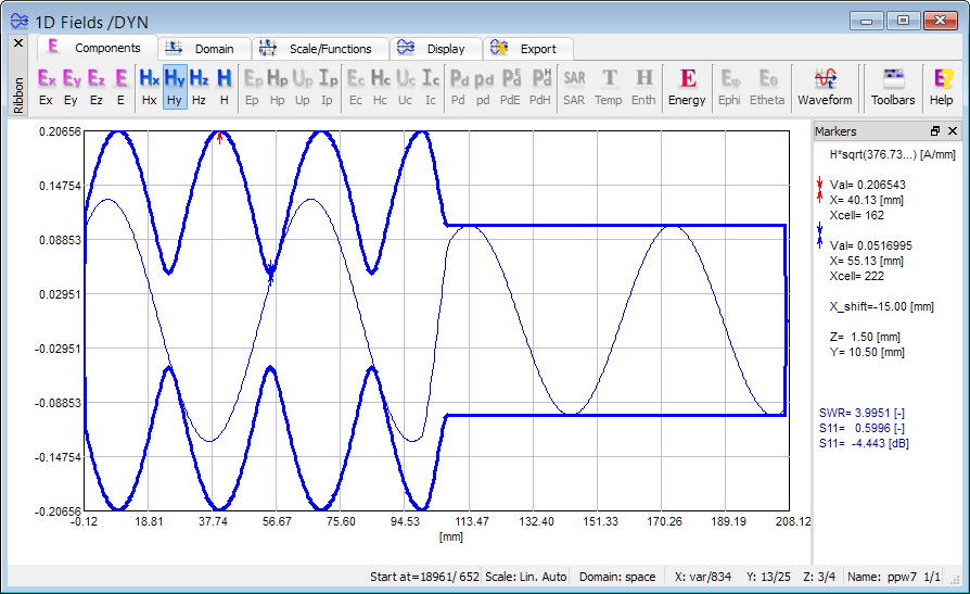
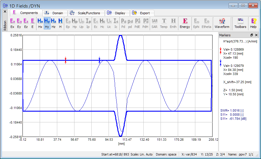
1D view of Hy field component distribution at 5GHz (instantaneous and envelope values).
The above displays show that the concrete slab placed in the line is not matched to the circuit, what results in a partially standing wave.
Impedance maching - half wavelength transformer
In the second case thickness of the concrete slab has been increased to 15 mm, which corresponds to half wavelength at 5GHz.
Distribution of time-maximum envelope of Ez field component at 5GHz.
Distribution of time-maximum envelope of Hy field component distribution at 5GHz.
1D view of Ez field component distribution at 5GHz (instantaneous and envelope values).
1D view of Hy field component distribution at 5GHz (instantaneous and envelope values).
Simulation results confirm theoretical calculations that using a half wavelength transformer assures impedance matching in the considered scenario.