1.3 Plane wave at the three media layered structure
Plane wave incident on three media boundary is the most interesting and complex case. The definitions of matching, quarter wavelength transformer and half wavelength transformer will be introduced and explained.
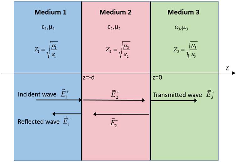
The media structure discussed in his paragraph is shown in Fig 18.
Fig 18 3-medium structure and normal plane wave incident.
In the considered case a plane wave propagating in medium 1 incidents at the boundary between medium 1 and 2, it is partially reflected (according to the rules described before) and then propagates further in medium 2 until it reaches the boundary of medium 3. At the medium 3 boundary a plane wave partially reflects and the remaining wave further propagates in medium 3. The wave reflected from the boundary of medium 2 and medium 3, propagating in medium 2, is partially transmitted to medium 1, thus it influences the amount of total reflection seen in medium 1.
The above reflections scenario can be simplified to a scenario of a plane wave incident at the boundary of two different media. It is done by introducing a variable describing the impedance of medium 3 transformed by a slab of medium 2 (it is an impedance “seen” by a wave incident at medium 2 boundary). This wave impedance is defined with the following formula:
![]()
giving:
![]()
The reflection coefficients are calculated for both boundaries as follows:
· Reflection coefficient G2,3(between medium 2 and 3)
![]()
· Reflection coefficient G1,2 (between medium 1 and 2)
![]()
The corresponding standing wave ratios are calculated as:
![]() ,
, ![]()
It is worth noting that in specific cases, ![]() component in the formula for transformed impedance equals 0 or
component in the formula for transformed impedance equals 0 or ![]() . Those situations will be considered below.
. Those situations will be considered below.
1.3.1.1 Quarter wavelength transformer
When the thickness (d) of medium 2 is equal to ¼ of a wavelength in this medium (![]() ),
), ![]() component equals to:
component equals to:
The formula for transformed impedance simplifies to:
![]()
Please note that the tangent function is periodic with period equal to p, so the above formula is correct for medium slab thicknesses of ![]() , where n is an absolute positive number.
, where n is an absolute positive number.
1.3.1.2 Half wavelength transformer
When the thickness (d) of medium 2 is equal to half of a wavelength in this medium (![]() ),
), ![]() component equals to:
component equals to:

The formula for transformed impedance simplifies to:
![]()
In this case the above formula is correct for slab thicknesses of ![]() , where n is an absolute positive number.
, where n is an absolute positive number.
The wave transformers introduced above are commonly used for impedance matching of different media. This means that the parameters of medium 2 are chosen to assure no reflections in medium 1.
Quarter wavelength transformer allows matching media of different impedances providing that the impedance of the transformer material equals:
![]()
Half wavelength transformer is transparent for the wave as long as its thickness equals to ![]() at a chosen frequency.
at a chosen frequency.
The objectives of this paragraph are:
· Analysis of the fields’ envelopes for three media layered structure
· The design of impedance matching in three media layered structure