2.6.3 Drawing the structure
At this stage we will be creating the project geometry. First step that needs to be accomplished is choosing the units that will describe the geometry. To do that we go to Model tab and from Units ![]() button we choose Millimetres. The same can be done in the Basic tab in the Circuit Settings dialogue.
button we choose Millimetres. The same can be done in the Basic tab in the Circuit Settings dialogue.

The dimensions of the waveguide are as follow:

To draw the structure we go to Geometry tab. We start from drawing the waveguide’s inside. We need to draw only the inside of the structure (the surrounding medium is metal), thus we start from the air block, which stands for the waveguide’s inside. To draw the waveguide we press Create a Box ![]() button in the Primitives section and a dialogue appears.
button in the Primitives section and a dialogue appears.
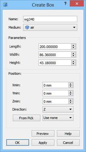
We set the object’s name to “wg340”. From the Medium combo box we choose air. Now we can proceed to setting the dimensions of the waveguide’s inside according to the picture above. With Position set to (0,0,0) the waveguide will be drawn so that its lower right corner is placed at this coordinates. After pressing OK button the waveguide’s inside appears in the project.
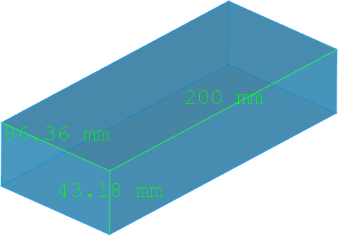
For better visualisation of the inside of the waveguide, we change its transparency by selecting wg340 object on the Tree View, and changing Transparency in the View tab in Property Editor to 50.

Previous step: Defining the type of the structure and background medium.
Next step: Drawing the ports.