3.3 Mode TM01
In this part of the tutorial the fields’ distribution for the TM01 mode in a circular waveguide is presented. As previously, the waveguide in 30 cm long and its radius is 10 cm. The cutoff frequency for the considered mode is 1.148 GHz, thus the waveguide is excited at 2 GHz, which is above the cutoff frequency. The length of the waveguide corresponds to 1.5 of guide wavelength.
The waveguide model is contained in cir_TM.QWpro scenario. For fields visualisation the model can be loaded in QW-Modeller, from where the electromagnetic simulation in QuickWave can be run.
Press ![]() button in 2D/3D Fields tab of QW-Simulator to open fields visualisation window. The consecutive displays shown in Figs. 10-13 may be viewed by pressing
button in 2D/3D Fields tab of QW-Simulator to open fields visualisation window. The consecutive displays shown in Figs. 10-13 may be viewed by pressing ![]() button for several times (once for obtaining each of the following displays). For the visualisation convenience the display windows may be maximised.
button for several times (once for obtaining each of the following displays). For the visualisation convenience the display windows may be maximised.
The TM mode means that there is no magnetic field component in the direction of wave propagation. The values of m and n indexes indicate that the transverse magnetic field has only an axial component (n=1), thus the transverse electric field has only a radial component. Fig. 10 and Fig. 11 show the transverse electric and magnetic fields’ distributions respectively. Fig. 12 and Fig. 13 present the distribution of the electric and magnetic fields along the waveguide in ZX plane (cross section in the middle of the waveguide). It can be clearly seen that only the electric field has a longitudinal component (along the direction of wave propagation). It is also well visible that the waveguide’s length is 1.5 of guide wavelength since three wave halves can be recognised in the fields’ distributions in ZX plane. The fields’ distributions in ZY plane are the same as in ZX plane since the TM01 mode is characterised by an axial symmetry.
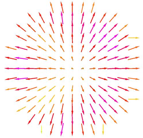
Fig. 10 A distribution of electric field for TM01 mode in a cross section of circular waveguide (YX plane).

Fig. 11 A distribution of magnetic field for TM01 mode in a cross section of circular waveguide (YX plane).
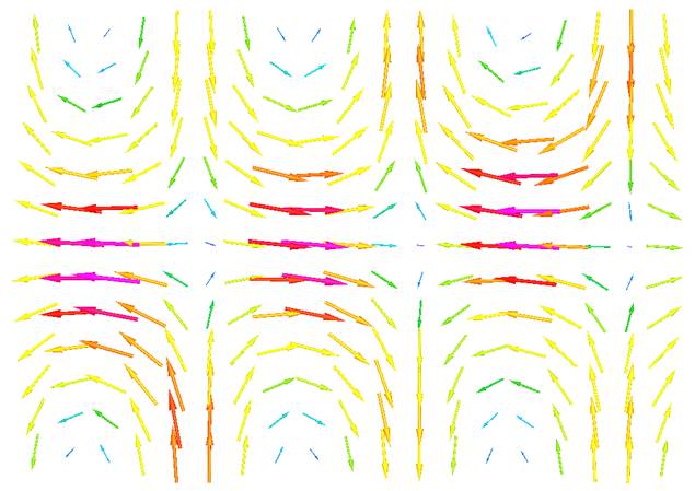
Fig. 12 A distribution of electric field for TM01 mode along the circular waveguide (ZX plane – in the middle of the waveguide).
 l
l

Fig. 13 A distribution of magnetic field for TM01 mode along the circular waveguide (ZX plane – in the middle of the waveguide).