3.4.4 Drawing the ports
In this step we need to draw and define the ports. In this case we need to define two ports, input and output with fundamental TE11 mode excitation.
To define the ports we need to go to Model tab. As a first one, we will define the waveguide input port. For that purpose we press Transmission Line ![]() commands button and choose Insert Transmission Line Source
commands button and choose Insert Transmission Line Source ![]() command.
command.

The following dialogue will appear.
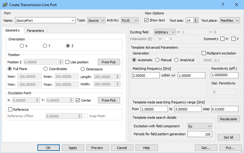
We set the name of the port to SourcePort. The default Type and Activity of the port are properly set for this case. The Orientation should be changed to Z. Full Plane option sets the port dimensions equal to the bounding dimensions of the entire project in the directions perpendicular to the port orientation what is suitable in this case. We uncheck the Reference option – it is not necessary since we do not calculate S-Parameters.
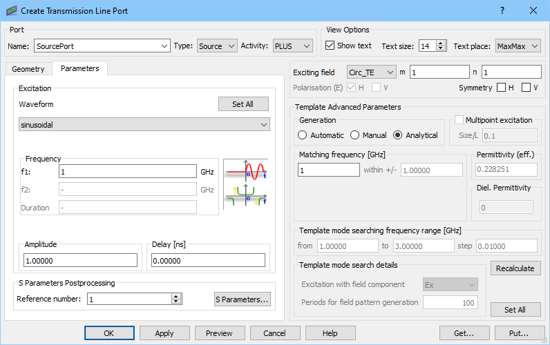
In the Parameters tab we set sinusoidal excitation at 1GHz. We excite the structure with a fundamental TE11 mode by setting Analytical generation, choosing Circ_TE from the Exciting field and setting m and n indexes to 1. Pressing OK button accepts the settings.

Now press Transmission Line ![]() commands button and choose Insert Transmission Line Load
commands button and choose Insert Transmission Line Load ![]() command.
command.

The following dialogue will appear.

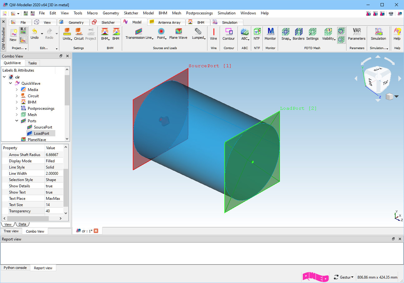
We set the name of the port to LoadPort. The default Type of the port is properly set for this case. The Orientation should be changed to Z. We should also change Activity to MINUS (please note that when Full Plane option is checked, port will change its position to the opposite side of the project). We uncheck the Reference option – it is not necessary since we do not calculate S-Parameters.

In the Parameters tab we set sinusoidal excitation at 1 GHz. We excite the structure with a fundamental TE11 mode by setting Analytical generation, choosing Circ_TE from the Exciting field and setting m and n indexes to 1. Pressing OK button accepts the settings.
The LoadPort can be also set by creating a copy of SourcePort and changing its parameters.
Previous step: Drawing the structure.
Next step: Setting boundary conditions.