4.2 Drawing the ports
After preparing the entire geometry of the microstrip line filter we can draw and configure the ports. We deal with a transmission type of structure thus, we need to define two ports (input and output) to be able to calculate characteristics of the filter.
In this case we assume that the structure is terminated with the absorbing boundary conditions at the upper and lower substrate edges (along Y axis) and above the structure (along Z axis) at a distance of 8 mm from the ground plane. The ports are located along X axis.
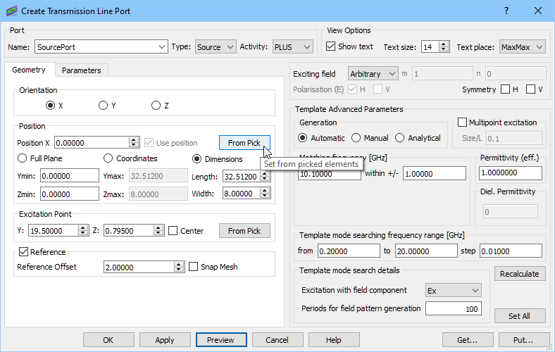
Firstly, we define the input port by choosing Insert Transmission Line Source from Transmission Line button. The port orientation is X and by default its dimensions are the same as the substrate dimensions in Y and Z directions. Since we want the height of the entire structure to be 8 mm (along Z axis) we need to extend port’s dimension in Z direction. For that purpose we choose Dimensions option and set Width along Z axis to 8 mm.
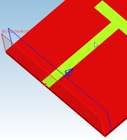
The excitation point should be placed on the strip, thus we select the strip and press From Pick in the Excitation Point section. Now the Z coordinate of the excitation point is 0.795 mm and we should correct the Y coordinate to 19.5 mm (the default position is chosen with respect to strip’s bounding box).
Create Transmission Line Port dialogue with port dimensions settings.
Now we can proceed to configuring the port parameters. We set the Reference Offset to 2 mm, switch to Parameters tab and set the other settings as below.
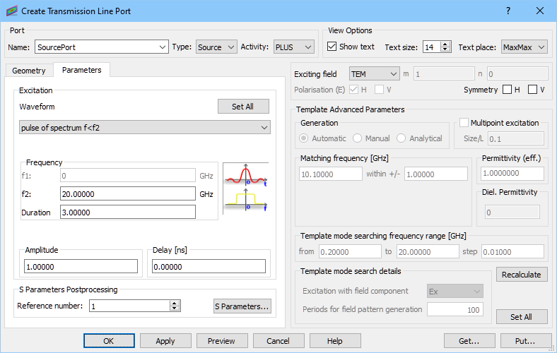
Create Transmission Line Port settings for input port.
We define the output port in the similar way and we modify the value of Y coordinate of the excitation point to 13 mm.
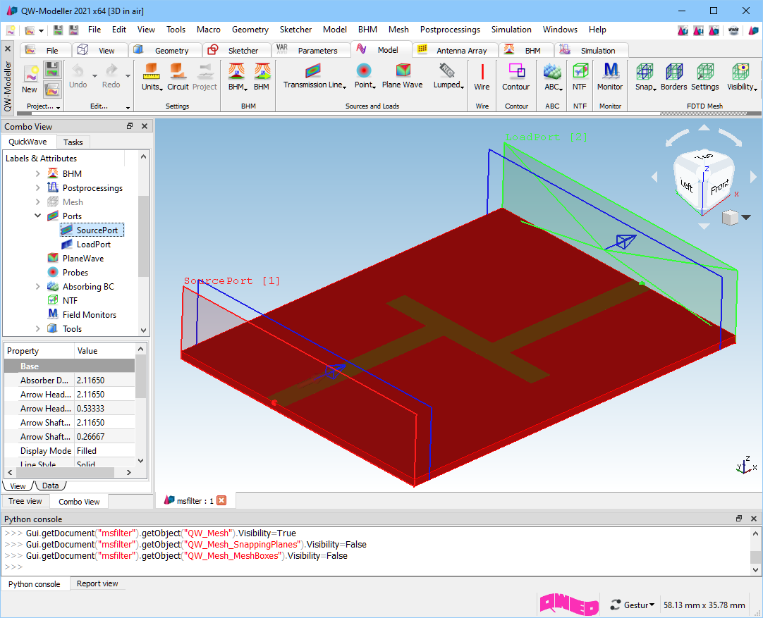
Microstrip line filter with ports defined.
Previous step: Drawing the structure.
Next step: Creating ABC MUR Walls.