5.4 Setting up the mesh
Having the structure’s geometry and the ports defined we can now set up the mesh. To do that, in Model tab we press the Settings ![]() button. The following dialogue will appear.
button. The following dialogue will appear.

Mesh Setttings dialogue for waveguide to coaxial line transition.
We set the following cell sizes in X, Y and Z direction respectively: 0.4 mm, 0.4 mm and 0.5 mm. The meshing will be enforced in the entire project space.
In addition, Snap to Metal Geometry option is checked in all directions, thus we do not have to enforce mesh snapping planes at the inner conductor vertexes manually to make sure that special models for fields’ singularities will be taken into account.
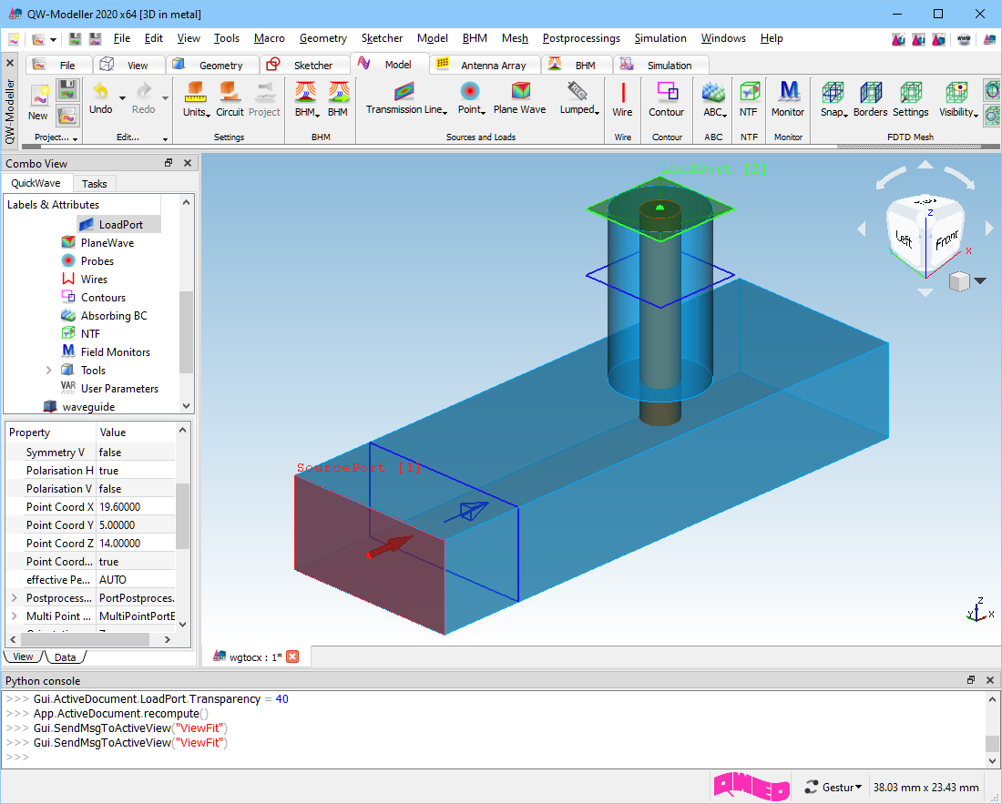
Waveguide to coaxial line transition with meshing set up.
Previous step: Drawing the ports.
Next step: Defining post-processings for simulation.