5.3 Plane Wave Box
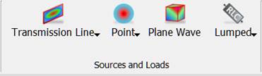
The Plane Wave button ![]() available in the Model tab allows introducing Plane Wave Boxes, which are auxiliary surfaces used for exciting an incident plane wave. After pressing Plane Wave button the Create Plane Wave Box dialogue appears. Similarly as in the case of Create Transmission Line Port and Create Point Port, there are Geometry and Parameters tab available on the left side of the dialogue.
available in the Model tab allows introducing Plane Wave Boxes, which are auxiliary surfaces used for exciting an incident plane wave. After pressing Plane Wave button the Create Plane Wave Box dialogue appears. Similarly as in the case of Create Transmission Line Port and Create Point Port, there are Geometry and Parameters tab available on the left side of the dialogue.

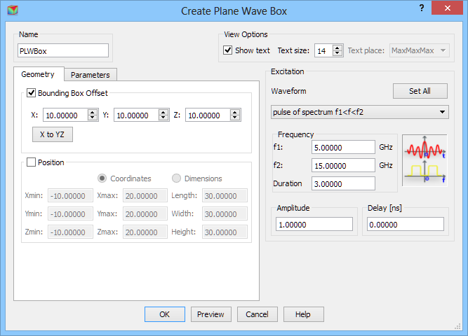
In the Geometry tab the user needs to define the dimensions of the Plane Wave Box. It can be done in two ways. First one is using Bounding Box Offset option, where the Plane Wave Box is drawn at the defined offset from the bounding box of the project structure. The offset is defined in project units for each direction and applies to each side from the structure. For the data in a given dialogue, the Plane Wave Box dimension in each direction will be 20 units bigger than the bounding box of the structure in the project. Please note that if the project contains only the geometry, the bounding box is determined by this geometry. If there is a NTF Box surrounding the geometry, the bounding box is determined by the NTF Box dimensions. If the user wants to place the Plane Wave Box “inside” the NTF Box, the second option for defining the Plane Wave Box dimensions should be used. In cases where the Absorbing Box is already defined in the project, the Plane Wave Box by default will be drawn in half distance between Absorbing Box and the geometry (Absorbing Box, when used, must be the most outer object in the project). If the default values of the offset are changed, the offset is calculated from geometry bounding box.
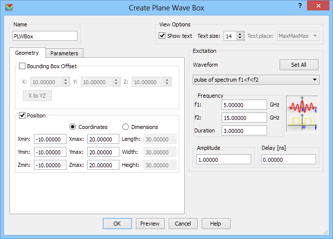
Second solution is using Position option, where the user can choose Coordinates or Dimensions. While using Coordinates option the MinMax coordinates of the Plane Wave Box in each direction should be defined. For the Dimensions option, length, width, and height of the Plane Wave Box should be given together with the Min coordinates at which the box geometry starts.
Parameters tab allows setting the incident wave as TEM (plane wave), B3D (a 3D Gaussian beam with Gaussian field variation in the plane perpendicular to the direction of incidence) and B2D (a 2D Gaussian beam; in the plane perpendicular to the direction of incidence; it has Gaussian field distribution in one direction and constant field in the direction perpendicular to it), incidence direction, etc.
The Incident frame is active for all illumination types. There are three angles to be chosen:
- j (Phi) – azimuthal angle of the direction of wave propagation,
- q (Theta) – elevation angle of the direction of wave propagation,
- Polarisation – polarisation angle of the electric field.
The Beam3D is active for B3D and B2D. It allows defining the position of the neck centre of the beam (NeckX, NeckY, NeckZ in the project units) and neck diameter (N_dia in the project units).
The Beam2D is active only for B2D. It allows defining Angle of variation of the beam field in the plane perpendicular to the direction of propagation, in the same convention as Polarisation is defined.
The Amplitude applies to a square root of surface power density, i.e., a square root of the Poynting vector amplitude of the incident wave.
It is advised to refer to Free space incident wave for detailed discussion regarding free space excitation with a plane wave or Gaussian beam.
In the Walls activity frame the user can supress activity of the walls of the Plane Wave Box in any direction, by unchecking an appropriate checkbox. Please note that the Plane Wave Box excites the wave towards the circuit and the checkboxes in Wall activity frame stand for the activity in a particular direction, e.g. –X checked means that the Plane Wave Box wall exciting the wave in –X direction is active; if we uncheck this option it will disable this wall.
The Background medium frame, placed on the right side of the Add Plane Wave Box dialogue allows defining material parameters of the medium in which the Plane Wave Box is placed. Please note that it is necessary to set up appropriately those parameters in scenarios where Plane Wave Box is placed in medium other than air, otherwise the calculations might be not trustworthy.
The Waveform frame enables setting the excitation parameters like, Waveform, Frequency Range, Amplitude, and Delay. See Waveform chapter for more information.
Python code
The python code, which can be useful when creating project scripts, generated by Create Plane Wave Box dialogue for default parameters:
from FreeCAD import Base
QW_Modeller.addQWObject("QW_Modeller::PlaneWaveBox","PLWBox")
App.ActiveDocument.PLWBox.OffsetX = 10.00000
App.ActiveDocument.PLWBox.OffsetY = 10.00000
App.ActiveDocument.PLWBox.OffsetZ = 10.00000
App.ActiveDocument.PLWBox.Length = 20.00000
App.ActiveDocument.PLWBox.Width = 20.00000
App.ActiveDocument.PLWBox.Height = 20.00000
App.ActiveDocument.PLWBox.Placement = Base.Placement(Base.Vector(0.00000,0.00000,0.00000),Base.Rotation(0.00000,0.00000,0.00000,1.00000))
Gui.ActiveDocument.PLWBox.ShowText = True
Gui.ActiveDocument.PLWBox.TextSize = 14
App.ActiveDocument.PLWBox.Phi = 0.00000
App.ActiveDocument.PLWBox.Theta = 90.00000
App.ActiveDocument.PLWBox.Polarisation = 0.00000
App.ActiveDocument.PLWBox.Illumination = "TEM"
App.ActiveDocument.PLWBox.NeckOriginX = 0.00000
App.ActiveDocument.PLWBox.NeckOriginY = 0.00000
App.ActiveDocument.PLWBox.NeckOriginZ = 0.00000
App.ActiveDocument.PLWBox.NeckDiameter = 1.00000
App.ActiveDocument.PLWBox.AngleOfVariation = 0.00000
App.ActiveDocument.PLWBox.WallXMinus = True
App.ActiveDocument.PLWBox.WallXPlus = True
App.ActiveDocument.PLWBox.WallYMinus = True
App.ActiveDocument.PLWBox.WallYPlus = True
App.ActiveDocument.PLWBox.WallZMinus = True
App.ActiveDocument.PLWBox.WallZPlus = True
App.ActiveDocument.PLWBox.Excitation = QW_Modeller.PlaneWaveExcitation(QW_Modeller.DriveFunction(QW_Modeller.Waveform('delta'),1.00000,0.00000,1.00000,0.00000))
App.ActiveDocument.recompute()
Gui.SendMsgToActiveView("ViewFit")