5.6 Contour
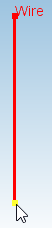
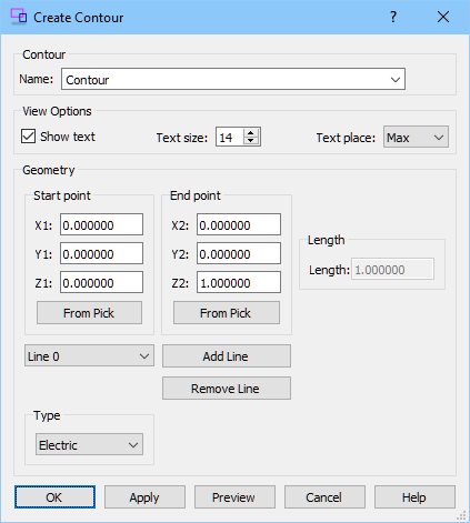
The Contour button ![]() available in the Model tab allows introducing contours. After pressing Contour button the Create Contour dialogue appears. The contour can consists of set of connected parts which starts at Start point and ends at End point defined either with X,Y,Z coordinates. Start point and End point can be also defined done by selecting of vertex of previously defined object(see Selecting Objects for more information) and using From Pick option for currently drawn contour. The next part of contour can be added by Add Line. The Type frame allows choose the contour type: Electric (for E-field integration) or Magnetic (for H-field integration).
available in the Model tab allows introducing contours. After pressing Contour button the Create Contour dialogue appears. The contour can consists of set of connected parts which starts at Start point and ends at End point defined either with X,Y,Z coordinates. Start point and End point can be also defined done by selecting of vertex of previously defined object(see Selecting Objects for more information) and using From Pick option for currently drawn contour. The next part of contour can be added by Add Line. The Type frame allows choose the contour type: Electric (for E-field integration) or Magnetic (for H-field integration).

Python code
The python code, which can be useful when creating project scripts, generated by Create Wire dialogue for default parameters:
from FreeCAD import Base
QW_Modeller.addQWObject("QW_Modeller::Contour","Contour")
App.ActiveDocument.Contour.listofendvectors = [Base.Vector(0.00000, 0.00000, 1.00000), Base.Vector(0.00000, 1.00000, 1.00000), Base.Vector(0.00000, 1.00000, 0.00000)]
App.ActiveDocument.Contour.listofstartvectors = [Base.Vector(0.00000, 0.00000, 0.00000), Base.Vector(0.00000, 0.00000, 1.00000), Base.Vector(0.00000, 1.00000, 1.00000)]
App.ActiveDocument.Contour.Type = 0
App.ActiveDocument.Contour.LineLengths = [1.00000,1.00000,1.00000]
Gui.ActiveDocument.Contour.ShowText = True
Gui.ActiveDocument.Contour.TextSize = 14
Gui.ActiveDocument.Contour.TextPlace = 1
App.ActiveDocument.recompute()
Gui.SendMsgToActiveView("ViewFit")