12.4 Loops in UDO scripts
When we want to specify an ordered distribution of lines or elements, we need to create a loop structure. In the UDO language the “if” and “while” instructions can be used for this purpose. They have the following syntax:
Syntax of loops
· if <logical expression> do .... endif; - Instructions between do and endif are interpreted if logical expression is true.
· while <logical expression> do ... endwhile; - Instructions between do and endwhile are executed in loop as long as logical expression is true.
Additional remarks
There is a very important difference between the equality sign “==“ used in logical expressions and the substitution sign “=“ used in equations. Using the later one in the logical expression will actually execute the substitution. Thus it will not only cause incorrect loop operation but may change the operation of the rest of the UDO script.
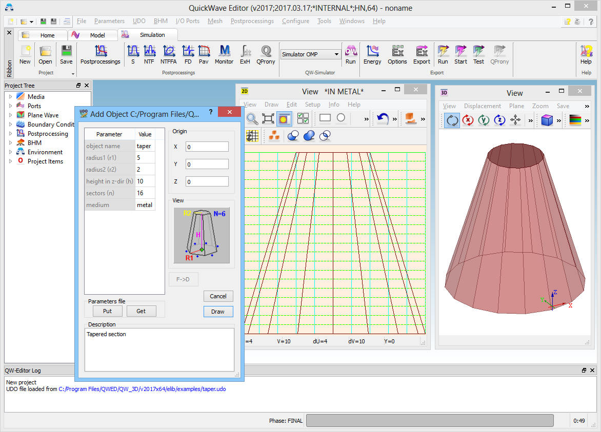
The following example will show the use of the while loop in generation of a combined element of circular bottom and top.
comment="Tapered section";
bitmap="taper.bmp";
PAR("object name",onam,"taper");
PAR("radius1 (r1)",r1,5);
PAR("radius2 (r2)",r2,2);
PAR("height in z-dir (h)",h,10);
PAR("sectors (n)",n,16);
PAR("medium",med,"metal");
ENDHEADER;
TEST(n>2,"n should be greater than 2");
step=360/n;
OPENOBJECT(onam);
ELEMENT(z,0,5,med,Taperb,IN); #bottom
NEWLINE(x+r1,y,x+r1*cos(step),y+r1*sin(step));
i=3;
while i<=n do
ADDLINE(x+r1*cos((i-1)*step),y+r1*sin((i-1)*step));
i++;
endwhile;
CLOSELINE;
ENDELEM;
ELEMENT(z+h,0,6,med,Taperb,IN); #cover
NEWLINE(x+r2,y,x+r2*cos(step),y+r2*sin(step));
i=3;
while i<=n do
ADDLINE(x+r2*cos((i-1)*step),y+r2*sin((i-1)*step));
i++;
endwhile;
CLOSELINE;
ENDELEM;
CLOSEOBJ;
Go to next Defining ports, boxes, mesh snapping planes, postprocessing and circuit parameters chapter.
Back to Syntax of the User Defined Object (UDO) language chapter.