6.1.5 Antenna 3D Parameters Panel
The Antenna 3D Parameters panel contains a set of options for 3D Radiation Pattern, display and Colour Bar options and Structure switches.
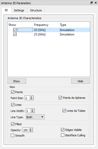
The list contains all 3D radiation patterns that are available. If the Show checkbox is checked, then the characteristic is displayed.
The View frame allows setting the display parameters for the selected characteristic in the list.
The Points frame contains the following options for the points representation of the antenna characteristic:
Point Size – defines the size of the point
Points As Spheres – when checked, points will be of the sphere shape and the square shape otherwise
The Lines frame contains the following options for the lines representation of the antenna characteristic:
Line Width – defines the width of the line
Line Type – defines the type of lines
Lines As Tubes – when checked, lines will be of tube shape and the flat line otherwise
The Filled frame contains the following options for the filled representation of the antenna characteristic:
Smooth – when checked, the colours inside the cell are approximated
Light – when checked, the enables light illumination of the display
Edges Visible – when checked, additional lines between cells will be shown
Backface Culling – when checked, the back sides of the display will be hidden

In the Show/Hide frame the visibility of elements in the display can be selected:
Planes/Sphere – circles plot indicating the Phi plane, the Theta plane and the plane containing the reference axis and perpendicular to the Theta plane
Arrows – an axes of Cartesian coordinates system, perpendicular to Phi plane, Theta plane or perpendicular to the reference axis plane (Ref. Axis Plane), Phi unit vector and Theta unit vector
Text – texts describing the visible Arrows
The Colour Bar frame (when checked, the Colour Bar widget will be shown) allows setting the parameters for the Colour Bar widget:
Discretize – when checked, the number of colours is defined
Title Font – when checked, the title containing component name and units will be displayed with the specified font size
Ratio – specifies the size of the widget
Horizontal – when checked, the widget will be placed horizontally
Component – when checked, the component information will be shown in the title
The Labels frame allows setting the labels of the Colour Bar widget:
Labels Nb – specifies the number of values labels
Labels Font -specifies the size of the font
Decimal Places – defines number of decimal places
Labels Left – when checked, labels will be shown on the left side or on the bottom of the widget
The Info frame (when checked, the Info widget will be shown) allows setting the parameters for the info widget:
Text Font –the text will be displayed with the specified font size
Text Colour –the text will be displayed with the specified colour
Background Colour – the background colour of the Info widget

The Elements frame allows setting the parameters for the geometrical objects and the Ports & Boxes frame allows setting the parameters for all non-geometrical simulation objects like, e.g. transmission line ports, ABC wall/box, NTF box, Field Monitors etc.
The Points frame contains the following options:
Point Size – defines the size of the point
The Lines frame contains the following options:
Line Width – defines the width of the line
Opacity – defines the translucency for the lines
The Filled frame contains the following options:
Opacity – defines the translucency for the solid
Smooth – when checked, the colours inside the cell are approximated
The Scale frame allows zooming in/out the project structure plot
The Move frame allows moving the project structure plot in X, Y and Z direction.