 b)
b) 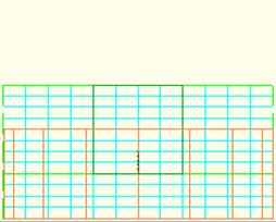 c)
c) 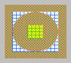
2.12.2 When we do not need Join operations
An element inside another one
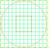
First of all note that the Join operations are being performed on slices in XY plane. Thus when deciding if such an operation is needed we should consider only if the intersection takes place in any of the XY plane slices. Let us consider example ..\Various\Joinex\jo3.pro presented in Fig. 2.12.2-1 in which a quartz parallel piped is partially inserted into a metal cylinder. Formally it is also an incorrectly defined structure. There is a part of the space attributed to both quartz and metal. However, the SAT files Viewer (Fig. 2.12.2-2a) and 3D Windows of QW-Editor (Fig. 2.12.2-2b, Fig. 2.12.2-2c) display the picture in accordance with presumed intentions that the part in question is filled with quartz. But the most important is that the QW-3D mesher always assumes that with one XY=plane contour completely included in another one, the medium of the inner contour prevails. As a result we have the correct meshing of the structure as shown in Fig. 2.12.2-1c. We do not need to perform the Join operation in such a case.
a) b) c)
Fig. 2.12.2-1 QW-Editor pictures of jo3.pro in 2D windows in horizontal XY-plane (a), in vertical XZ-plane (b) and QW-Simulator Test Mesh picture in the middle of the structure.
a)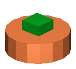 b)
b)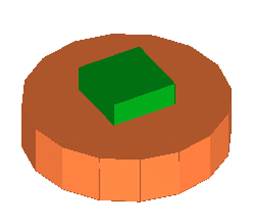 c)
c)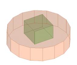
Fig. 2.12.2-2 Pictures of jo3.pro in SAT files Viewer (a), 3D solid view (b) and 3D solid view with Transparent covers (c).
An element internally tangential to another one
Let us now consider a structure of ..\Various\Joinex\jo4.udo presented in Fig. 2.12.2-3. A block of quartz is internally tangential to the block of metal. The problem here is the left border in which there are conflicting declarations about medium visible on the right side. One element is supposed to enforce quartz and the second one to enforce metal. The software detects that the structure is internally tangential and assumes that the medium of smaller segment of common boarder is prevailing. That is why it is correctly meshed as seen in Fig. 2.12.2-3c.
a)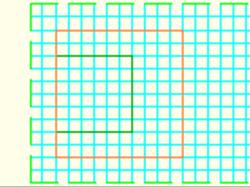 b)
b) 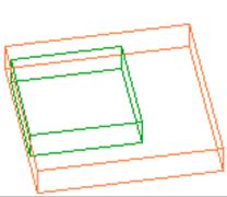 c)
c) 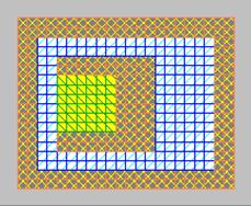
Fig. 2.12.2-3 QW-Editor pictures of jo4.pro in 2D windows in horizontal XY-plane (a), in a 3D window (b) and QW-Simulator Test Mesh picture (c) after automatic meshing without Cut operation.
Note however that this criterion does not work in the case when both elements have in common an entire wall as exemplified by ..\Various\Joinex\jo5.pro and shown in Fig. 2.12.2-4. In such a case the Cut operation is needed. Otherwise we may obtain incorrect meshing as presented in Fig. 2.12.2‑4c.
a)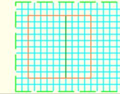 b)
b) 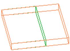 c)
c) 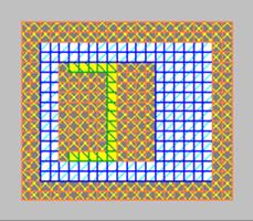
Fig. 2.12.2-4 QW-Editor pictures of jo5.pro in 2D windows in horizontal XY-plane (a), in a 3D window (b) and QW-Simulator Test Mesh picture (c) after automatic meshing without Cut operation.
Intersecting elements made of the same medium
Let us consider now two intersecting elements made of the same medium considered in ..\Various\Joinex\jo6.pro and shown in Fig. 2.12.2-5. In QW-3D versions up to version 2.0 we needed to perform Glue operation on them to have a fully correct meshing. The software makes a kind of “glue” operation on such elements prior to meshing. Thus the meshing result is fully correct (as presented in Fig. 2.12.2-5c) without Glue operation enforced by the user.
a)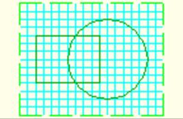 b)
b) 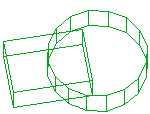 c)
c) 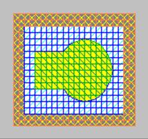
Fig. 2.12.2-5 QW-Editor pictures of jo6.pro in 2D windows in horizontal XY-plane (a), in a 3D window (b) and QW-Simulator Test Mesh picture (c) after automatic meshing without Glue operation.
The above statement is an important indication on how to apply some of the library objects like for example the strip shapes of the library planar. It often happens that we want to put two strip segments adjacent to each other. An accidental microscopic slot in the junction can be very harmful to the meshing process and as a result to the accuracy of calculations. That is why whenever it is difficult to make the ends of the adjacent strips perfectly tangential, it is better to make them slightly overlapping then to risk appearance of some gaps between them.