1 Introduction to QW-V2D package
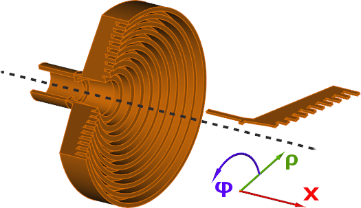
QW-V2D is one of specialised packages of QuickWaveTM family, which is applicable to the analysis of axisymmetrical circuits (which are also called Bodies of Revolution).
It has been proven [7] that the structures, which maintain axial symmetry of boundary conditions, belong the class of vector two-dimensional (V2D) problems. The total electromagnetic field in such structures can be decomposed into a series of orthogonal modes, of different angular field dependence of the cos(nj) or sin(nj) type, where j is angular variable of the cylindrical coordinate system and n=0,1,2… Each n-mode is analysed separately in QW-V2D. Under such assumptions the numerical analysis can be conducted in two space dimensions, over one half of the long-section of the structure, with n predefined as a parameter. Let us note that the n-mode defined above should not be confused with one mode of a circular waveguide. For example, one QW-V2D analysis with n=1 takes into account a composition of all circular waveguide modes TE1k and TM1m where k and m are arbitrary natural numbers.
QW-V2D utilises the conformal FDTD method in a vector two-dimensional formulation, expressed in cylindrical coordinates. It incorporates a range of unique models for curved boundaries, media interfaces, modal excitation, and parameter extraction.
QW-V2D can handle a variety of practical problems including:
· calculations of radiation patterns, gain, radiation efficiency, and return loss of axisymmetrical antennas of various types (horn, rod, biconical), rigorously taking into account irregular geometry, complicated corrugations, and inhomogeneous filling,
· calculations of radiation patterns and radiation resistance of small dipole or loop radiators, located at the axis of the cylindrical coordinate system,
· accurate S-parameter calculations of circular waveguide discontinuities, also in cases involving strong dispersion and multimodal propagation,
· determination of eigenfrequencies, Q-factors, and pure modal field patterns for shielded and open inhomogeneous axisymmetrical resonators, also in cases involving closely-spaced modes or whispering gallery modes,
· calculation of specific absorption rate in axisymmetrical bodies.
QW-V2D has been implemented on the basis of QW-3D, a three-dimensional simulation package by QWED, and a winner of the European Information Technology Prize in 1999. Thus, QW-V2D takes full advantage of the graphical user interface and modern programming techniques employed and validated within QW-3D. Moreover, the user experienced with either QW-V2D or QW-3D will find the operation of the other package straightforward.
QW-V2D comprises two main functional blocks:
· QW-Editor operating in a 2D regime, which allows graphical definition of a 2D long-section of the structure, mesh generation, and specification of simulation parameters via a convenient system of dialogues,
· QW-Simulator operating in a vector 2D regime, which conducts the FDTD calculations, extracts the desired frequency-domain parameters, and displays all the computed fields and results.
There are several ways of defining the 2D long-section shape of the considered structures in QW‑Editor:
- Manual definition of the shape and dielectric filling via simple mouse operations, menu commands, and ribbon or toolbar buttons.
- Writing a script in so called User Defined Object (UDO) language. This way is often most appreciated, because the UDO language allows definition of complicated parameterised shapes using variables, programming loops etc. Preparation of a UDO script may require some initial effort but offers a possibility of very fast and easy modification of the project in terms of shape and size of metal boundaries, number of various elements (like for example the number of horn corrugations), type and size of dielectric inserts etc. Parameterised shape definition described by the UDO language is also indispensable in the case of automatic optimisation using QW‑OptimiserPlus or other external optimisation tools.
- Using predefined User Defined Objects supplied by QWED in the object elib library. Standard installation of QW-V2D includes a directory elib with several subdirectories. They contain standard objects. Upon request of the customer QWED is ready to prepare additional customised objects. We believe also that customers will be generating their own objects to put them in one or several subdirectories of elib. It is important to note that the UDO language allows nesting of objects. Thus for example a high level objects describing an antenna system may include calls to lower level objects describing horn or reflector details. There is no limit on the number of levels of object nesting. Thus quite complicated object systems covering a large scope of antenna shapes can be created.
- Importing industrial CAD formats and in particular ACAD’s DXF format is another way of shape definition in QW-V2D. Standard version of QW-V2D incorporates DXF converter, which can read a DXF format file and convert it to a UDO script file. This is a convenient way of operation in an industrial environment. However, it also has some drawbacks. The resulting UDO script includes numerical (non-parameterised) values of coordinates of consecutive shape points and thus the shape cannot be easily modified within QW-V2D Editor. In practice this means that shape modifications need to be done in the software supplying *.dxf file to QW-V2D.
The above modes of definition of the shape of the investigated structure give a flexible ground for software application by different users. It is assumed that every user will find a favourable way of working with the software applying one or combination of several modes of operation.
Although QW-Editor automatically generates the FDTD mesh, the user is equipped with many means of controlling the meshing process, including the enforcement of global and local maximum cell size, mesh snapping planes, and mesh refinement in regions of expected rapid field variation.
QW-Simulator utilises state-of-the-art FDTD algorithms as well as many original models and procedures developed by the authors of the program during two decades of intensive research on the time-domain electromagnetic modelling. These specialised features are well represented by the publications listed in Chapter V2D 3. The following features should be emphasised:
· accurate and stable representation of curved metal boundaries [1] [3] [5], without FDTD time-step reduction,
· higher-order modelling of media interfaces [4] [6],
· wide-band modelling of skin effect in lossy metals [32],
· guaranteed spurious-free behaviour of the algorithm, also in the presence of strong spatial irregularities [35],
· matched modal excitation based on the field and impedance template [2] [11],
· an original system of S-parameter extraction incorporating differential decomposition of fields into incident and reflected waves [9], template filtering for desired mode extraction [11], and compensation for imperfect absorbing boundaries [9] [10],
· a novel variable source impedance technique for emulation of pure eigenmodes in inhomogeneous resonators [26],
· anisotropic boundary conditions (wire grids),
· a specialised procedure, which transforms the near fields simulated in cylindrical coordinates to the far fields in spherical coordinates [8].
QW-Simulator also offers many ways of visualisation of simulated fields and calculated circuit characteristics, including:
· various displays of instantaneous field values in the xr -, rφ- planes,
· various displays of two-dimensional field envelopes in the xr -, rφ- planes,
· various displays of instantaneous, maximum, and average SAR and dissipative power in the xr -, rφ- planes,
· field envelopes along any line parallel to the x- or r - axes,
· field variation along any contour,
· field variation in time at any point,
· S-parameters versus frequency in linear, quadratic or decibel scale, on Smith chart and in polar coordinates,
· radiation patterns versus angle, radiated power, and antenna efficiency for a set of frequencies.
QW-V2D allows storage of calculated fields and results on the disk. The available options include:
· exporting S-parameters in SupertCompact, Touchstone, CSV, SAC, and GRASP formats,
· saving S-parameters, eigenvalue charts, and antenna characteristics in text files,
· dumping instantaneous field values of all field components in text files,
· dumping 2D envelopes of selected field components in text files,
· dumping 1D envelopes of selected field components along a selected line in text files.
A powerful feature of QW-Simulator is freeze of simulation state. It permits interrupting the simulation and storing the simulator state with all its variables on disk. At any convenient time the user can resume the simulation at the broken point (for more information refer to Simulation Freeze).
QW-V2D can cooperate with optional modules: QProny, QW-OptimiserPlus, and S-Converter. QProny performs signal post-processing by a modified Prony method, extracting resonant frequencies and loaded Q factors. It is recommended for faster analysis of high-Q devices such as narrow-band circular-waveguide filters. QW-OptimiserPlus acts as a master program, sequentially calling QW-Editor and QW-Simulator. It modifies user-selected variables to minimise the goal function. Currently it can work with goal functions based on S-parameters, FD-Probing, radiation patterns and also it can invoke an external software module, export selected QW results to this module, and import a user-defined goal function calculated by the module. Its graphical interface is fully integrated with QW-Simulator. S‑Converter performs cascading/de-cascading or embedding/de-embedding operations on several S-parameter files [36] [44].
Detailed description of the optional modules QProny, S-Converter, and QW-OptimiserPlus is given in separate manuals. All modules are distributed by QWED.
QW-V2D can be used in multicore/multithread and GPU implementations of QW-Simulator [38] [43] what is a significant acceleration advantage.
QW-V2D is a multiplatform software package prepared in object-oriented C++ language under Qt (Qt is a multiplatform C++ GUI toolkit). Further in this Chapter, we shall concentrate on the hardware/system requirements and installation procedure for the most popular version of QuickWave, prepared for Microsoft Windows 7/8/8.1/10 operating system. For possibilities of application on other platforms, please contact QWED directly.