2.6.5 Setting boundary conditions
In the Model tab we press the Borders ![]() button. The Boundary Conditions dialogue will appear.
button. The Boundary Conditions dialogue will appear.
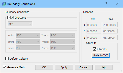
In the Boundary conditions frame we leave the default settings (Perfect Electric Conductor boundary conditions in all directions). Please note that boundary conditions’ indicators are visible when Boundary Conditions dialogue is opened or when visibility for Computational Borders is enabled. We will make Boundary Conditions indicators visible using Visibility ![]() button.
button.

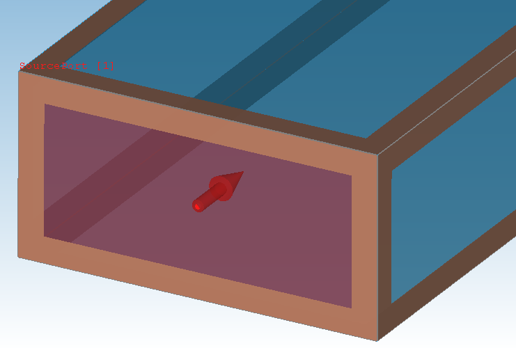
After zooming the display, we can observe that brown colour indicates PEC boundary conditions.
Previous step: Drawing the ports.
Next step: Setting up the mesh.