
5.1 Transmission Line Port
The Transmission Line button 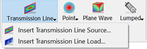 in the Model tab allows setting up the template ports. Under the Transmission Line drop-down button two possible options are available:
 ![]() and
and ![]() . After choosing
. After choosing ![]() option the Create Transmission Line Port dialogue appears.
option the Create Transmission Line Port dialogue appears.

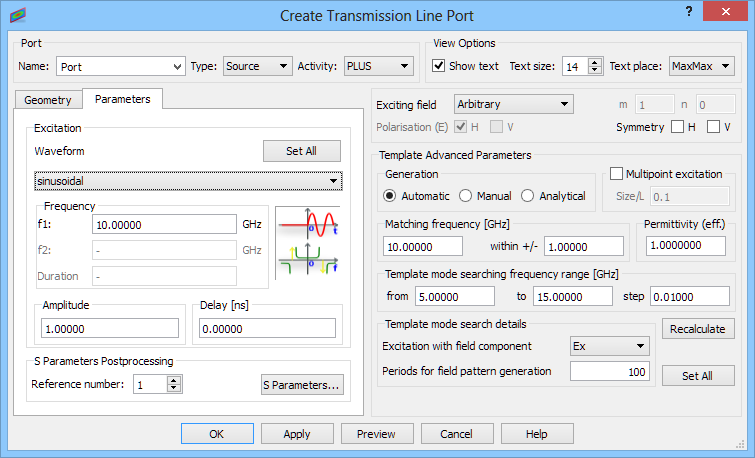
In the Port frame the user defines the name used to identify the port, its type (source or load) and activity (plus or minus). Further, in the View Options it is possible to determine whether the port should be signed by its name in the project window (Show text), a font size of the string (Text size) and its position by indicating the port corner (Text place).
On the left side of the dialogue, Geometry and Parameters tabs are placed. In the Geometry tab the user sets the port Orientation by choosing an appropriate axis. In the Position frame the position and dimensions of the port are set. There are two options available in this manner. First one, the user puts all data manually. To set the port position the Use position option needs to be checked and the position is defined explicitly. The in plane dimensions of the port can be set in three ways. Full Plane option sets the port dimensions equal to the bounding dimensions of the entire project in the directions perpendicular to the port orientation. Coordinates option allows introducing MinMax coordinates between which the port will be created/stretched out. Dimensions option allows defining port dimensions explicitly but requires also Min coordinates indicating where the port geometry starts.
The second option allows defining the port position and dimensions by indicating the element at which it should be created. The From Pick option causes that the port is placed at a bounding box of the selected element (e.g. at a plane, between selected edges or points). To use this option the user needs to firstly select the element in the project window and then press From Pick button.
The next frame, Excitation Point, corresponds to the position of the excitation point in the template port. By default, the excitation point is placed at the centre of the template port and Auto checkbox is checked. If it is required to change the default position the Auto option should be unchecked and an appropriate coordinates should be put in the adjoining fields. For the From Pick option an element in the project window should be firstly selected. This option places the excitation point in the centre of the selected element (e.g. in the centre of a plane, in the middle of the edge).
At the bottom of the Geometry tab, in the Reference frame, it is possible to decide whether the reference plane (for S-Parameters postprocessing) should be associated with the port. If yes the Reference checkbox should be checked and reference position (with respect to port plane) needs to be given in Reference Offset field. However, the software incorporates a Shift Reference function (available in QW-Simulator), which allows moving virtually the reference plane to any position (for example to that of the port).
In the Parameters tab, the Waveform frame enables setting the excitation parameters like, Waveform, Frequency Range, Amplitude, and Delay. There are several options for excitation Waveform. After choosing one of them its time domain shape and frequency domain spectrum are displayed schematically. There is however a way of obtaining precise information about the spectrum of the selected pulse. It is available with Power Available post-processing.

In the S-Parameters Postprocessing frame the number assigned to the reference plane associated with the port is given. This number can be freely changed by the user according to his preferences, although the source port must always have number 1 to assure proper S-Parameters calculations (for the scenarios with bigger number of sources, S-Parameters cannot be calculated). At this stage the user can pass to S-Parameters post-processing configuration dialogue by pressing ![]() button.
button.
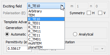
In the right part of the dialogue, parameters necessary for proper template mode generation (mode type, dominant field component, effective permittivity, etc.) has been gathered. The Exciting field contains the following mode type options:
It is advised to refer to Transmission line port excitation for more details regarding the exciting modes.
It should be noted that the transmission line ports require template mode generation. The template modes are divided into: dynamic templates and qusi-static templates. The quasi-static templates include TEM, multiTEM, and planeTEM modes. The dynamic template is used basically for waveguide modes. However, it is also applied for quasi-TEM modes in inhomogeneously filled lines at higher frequencies where dispersion effects become important. Dynamic template generation is in detail described in Dynamic templates and it is recommended to refer to this section for more information.
In case of dynamic template modes it is worth noting that:
· For the rectangular and circular waveguide modes explicitly listed under Exciting field, QW-Modeller can introduce the default parameters for QW-3D analysis. In QW-3D operation, for Automatic mode of dynamic templates generation, this capability is restricted to the following rectangular waveguide modes: TE10, TE01, TE11, TM11, and the following circular waveguide modes: TE11, TM01. In QW-V2D operation, this capability is restricted to the following circular waveguide modes: TMn1, TMn2, TEn1, TEn2, where n is angular variation defined for the project. In calculation of the default parameters the software assumes that the size of the port matches the size of the waveguide and that the waveguide is filled with air. If this is not true, the user should introduce the proper corrections to the set of parameters. It is advised to refer to Transmission line port excitation for more information regarding exciting modes.
· The alternative for the above procedure is Analytical mode of dynamic template generation. Using Analytical mode generation the user should set a required mode: Rect_TE, Rect_TM, Circ_TE or Circ_TM and values of mode indices m and n. Note that for Analytical mode the software assumes that the size of the port matches the size of the waveguide and the waveguide is filled with air. It is advised to refer to Transmission line port excitation for more information regarding exciting modes.
· For other modes, inhomogeneously filled waveguides or quasi-TEM lines at high frequencies the user should select the mode to be Arbitrary and set proper effective permittivity value (it is advised to refer to Transmission line port excitation for more information).
· For Automatic mode generation the software will try to generate template at the matching frequency, within a specified margin. Template mode searching range should include this frequency. A warning will be issued if the matching frequency cannot be found. It is advised to refer to Automatic dynamic templates for more information.
· For Analytical mode generation the software generates theorethical template shape at the matching frequency for set mode. A warning will be issued if the matching frequency cannot be found (matching frequency below cut-off frequency for given mode). It is advised to refer to Analytical dynamic templates for more information.
· For a general mn mode, the index m is assumed to correspond to: x dimension for ports located in the XY-plane or XZ-plane; y-dimension for the ports located in the YZ-plane.
· The Symmetry boxes H, V should be checked if only half of the waveguide has been drawn (with respect to the m or n index) utilising the corresponding symmetries of the circuit. This instructs the software to take double port dimension along m, n for calculating cutoff frequency, and thus effective permittivity, for the mn mode.
· Effective permittivity is calculated for the set matching frequency. It is calculated for air filled waveguide for the above given waveguide modes. If the user subsequently changes the matching frequency, effective permittivity for Automatic mode generation is not automatically recalculated. The simplest way to recalculate it is to re-select the desired mode. For the dielectric filled or higher order modes (Arbitrary option) it is user’s responsibility to calculate and set proper effective permittivity value. It is aadvised to refer to Transmission line port excitation for more details regarding this case and formulas for effective permittivity calculation.
For Analytical mode generation effective permittivity is recalculated automatically.
· Excitation field component - this is the field component used for dynamic template mode generation. It should be set in accordance with the expected template mode distribution as described in Dynamic templates (for practical example refer to Septum polariser as six-port with higher-order waveguide modes). This option is enabled for Automatic and Manual mode generation only.
· Periods for field pattern generation – relevant for Automatic mode generation only. A typical value sufficient for obtaining a steady state with sinusoidal excitation in most applications is about 100. However, the user is advised to observe the field distribution during the sinusoidal stage of the template generation process (see User Guide 3D: S-parameter extraction problems chapter) to find out if for his applications this number should be cut down (to save computing time) or increased (to get better accuracy of the final mode template). Three dependend numbers below are displayed as an information compatible with the previous version of dialogue.
In typical cases the template port is excited with a single excitation point, however there are specific cases when it is recommended to use the Mulipoint excitation to speed up the dynamic template generation process. The multipoint excitation option and its usage are in details described in Multipoint excitation.
It is advised to refer to Transmission line port excitation and Transmission line port termination for more information regarding both types of transmission line ports.
Python code
The python code, which can be useful when creating project scripts, generated by Create Transmission Line Port dialogue for default parameters:
from FreeCAD import Base
QW_Modeller.addQWObject("QW_Modeller::TemplatePort","Port")
App.ActiveDocument.Port.Length = 10.00000
App.ActiveDocument.Port.Width = 10.00000
App.ActiveDocument.Port.Placement = Base.Placement(Base.Vector(0.00000,5.00000,5.00000),Base.Rotation(0.50000,0.50000,0.50000,0.50000))
App.ActiveDocument.Port.Orientation = "X"
App.ActiveDocument.Port.Position = 0.00000
App.ActiveDocument.Port.Activity = "PLUS"
App.ActiveDocument.Port.Type = "Source"
App.ActiveDocument.Port.Reference = True
App.ActiveDocument.Port.SnapMeshToReference = False
App.ActiveDocument.Port.ReferenceOffset = 5.00000
App.ActiveDocument.Port.SymmetryH = False
App.ActiveDocument.Port.SymmetryV = False
App.ActiveDocument.Port.PointCoordX = 0.00000
App.ActiveDocument.Port.PointCoordY = 5.00000
App.ActiveDocument.Port.PointCoordZ = 5.00000
App.ActiveDocument.Port.PointCoordAuto = 1
Gui.ActiveDocument.Port002.ArrowShaftRadius = 0.20000
Gui.ActiveDocument.Port002.ArrowShaftLength = 2.00000
Gui.ActiveDocument.Port002.ArrowHeadRadius = 0.50000
Gui.ActiveDocument.Port002.ArrowHeadLength = 2.00000
Gui.ActiveDocument.Port002.AbsorberDepth = 2.00000
App.ActiveDocument.Port.effectivePermitivityMode = "AUTO"
App.ActiveDocument.Port.Excitation = QW_Modeller.TemplateExcitation(QW_Modeller.DriveFunction(QW_Modeller.Waveform('sinusoidal', 10.00000), 1.00000, 0.00000, 1.00000, 0.00000), 'Arbitrary', 'Ex', 1.0000000, QW_Modeller.TemplateGenerationConf('Automatic', (10.00000, 0.20000), (9.00000, 11.00000, 0.01000), 1.0000000, 100, 1, 0))
App.ActiveDocument.Port.MultiPointExcitation = QW_Modeller.MultiPointPortExcitation(0,"0.1")
App.ActiveDocument.Port.Postprocessing = QW_Modeller.PortPostprocessing(0,0,1)
Gui.ActiveDocument.Port.ShowText = True
Gui.ActiveDocument.Port.TextSize = 14
Gui.ActiveDocument.Port.TextPlace = 3
Gui.ActiveDocument.Port.Transparency = 40
App.ActiveDocument.recompute()
Gui.SendMsgToActiveView("ViewFit")