
7.2 Two rotating objects
The Single Object rotation mechanism allows only one object to be rotated during the heating. The Movement mechanism allows an arbitrary number of N rotating objects, each with its own rotation axis and speed. Requirements for setting such a project are:
· The project must contain N objects differing by name, so that they can be distinguished.
· The rotation (movement) parameters must be specified for each object separately.
· The cylinders sketched by the outermost vertices of the rotating objects must be non-overlapping. Any two cylinders may touch in the z-direction. In the xy-plane, a margin of at least two FDTD cells is recommended.
To demonstrate this feature, we first consider the heat_rota2_z.pro. It is physically equivalent to the heat_rota1.pro but differently set up in QW-Editor. The original Food object has its height decreased from 24 mm to 12 mm. At the level of its cover, another object FoodH (defined from the same library basic\cubo.udo) has its base. The two objects have the same shape in the xy-plane (their projections onto the xy-plane overlap) and the same height. They are made of two formally different media Food and FoodH, described by two *.pmo files, but the two sets of media parameters (and their initial temperature) are identical. Fig. 7.2-1 shows a general view of the scenario, Edit Rotation Axis dialogues setting the movement parameters for the two objects, and the resulting Heating Details dialogue confirming the movement settings in the Multiple Movements frame.
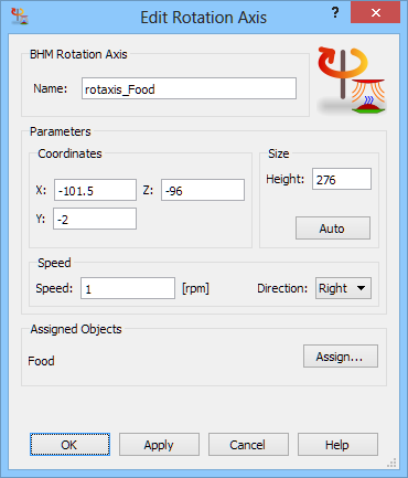

Fig. 7.2-1 View of the heat_rota2_z.pro with two objects shown in orange and green; Heating Details dialogue and its movement parameters settings in QW-Editor.
The exported *.ta3 (left in Fig. 7.2-2) and*.mv3 files (right in Fig. 7.2-2) now contain two sets of data for the two rotations. The fourth parameter line of the Modify_Media_Parameters_Rot_Ext task has two keywords: Rota Rota and parameters for the two rotations are given in the two columns below the Rota Rota line. In heat_rota2_z.mv3, there are two rows below the header line, specifying limits for the two rotating volumes, respectively. Note that the two objects span cylinders of equal radii (78.42…mm) from their respective axes, which in this case also coincide (as demonstrated by the *.ta3 file). The objects and their cylinders touch at the level of -204 mm.
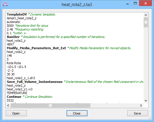
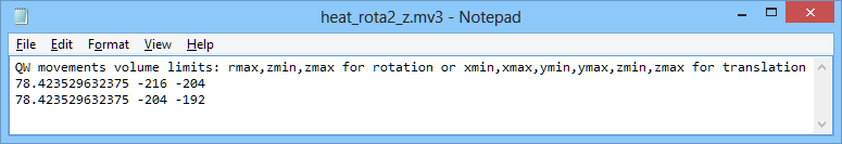
Fig. 7.2-2 Files exported by QW-Editor for the heat_rota2_z.pro: initial fragment of heat_rota2_z.ta3 and heat_rota2_z.mv3 with cylindrical space limits for the two rotations.
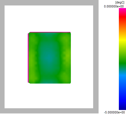
The project is saved as heat_rota2_z.pro and run. The results are identical as for the heat_rot1.pro. In particular, the final minimum and maximum temperatures after 12 BHM steps are -3.45422 and -1.97978 respectively for the 64-bit implementation of QW-BHM.
|
BHM iter. |
Min temp |
Max temp |
|
|
1 |
-4.99 |
-4.22 |
|
|
2 |
-4.92 |
-3.57 |
|
|
3 |
-4.81 |
-2.93 |
|
|
4 |
-4.75 |
-2.44 |
|
|
5 |
-4.72 |
-2.43 |
|
|
6 |
-4.46 |
-2.43 |
|
|
7 |
-4.24 |
-2.28 |
|
|
8 |
-4.01 |
-2.26 |
|
|
9 |
-3.85 |
-2.23 |
|
|
10 |
-3.71 |
-2.10 |
|
|
11 |
-3.60 |
-2.02 |
|
|
12 |
-3.45 |
-1.98 |
Fig. 7.2-3 Temperature in heat_rota2_z project, and final temperature pattern across the load (in -5÷0°C scale, in layer 8).
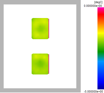
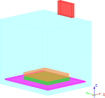
Consider now a scenario with two physically disconnected objects, each rotating around its own axis (which in this case is one of its vertices). Note that a distance of several cells in maintained between the two objects on the FDTD mesh. The scenario is stored in as heat_rota2_xy.pro file. Its movement parameters are set via Add Rotation Axis/Edit Rotation Axis dialogue and shown in its Heating Details dialogue (Fig. 7.2-4). Now the resulting minimum and maximum temperatures are -2.25155 and -1.48379.
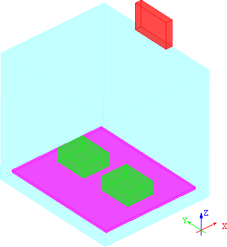
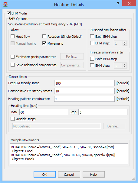
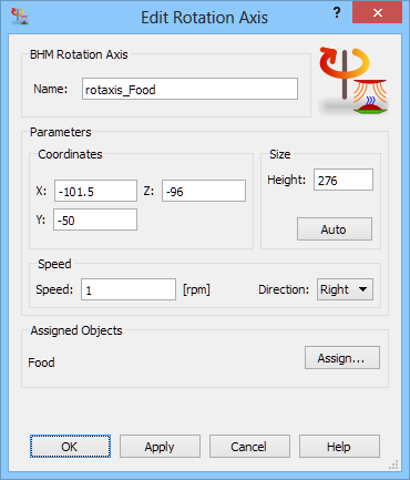
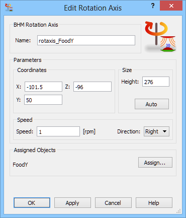
Fig. 7.2-4 View of the heat_rota2_xy.pro with two objects shown in green; Heating Details dialogue and its movement parameters settings in QW-Editor.
To create the heat_rota2_xy.pro example, we have gradually proceeded from the simple static heat.pro through a rotating scenario (where the heated element has to be re-defined as an object in the QW-Editor sense), then through the generalised movement (where the movement parameters needed to be set up) up to the point of adding the second moveable object. As a result, heat_rota2_xy.pro is constructed. In many cases, it may be more convenient to nest these commands within one master UDO script.
BHM iter. |
Min temp |
Max temp |
|
|
1 |
-4.97 |
-3.88 |
|
|
2 |
-4.91 |
-2.96 |
|
|
3 |
-4.78 |
-2.50 |
|
|
4 |
-4.62 |
-2.31 |
|
|
5 |
-4.44 |
-2.12 |
|
|
6 |
-4.07 |
-2.01 |
|
|
7 |
-3.79 |
-1.93 |
|
|
8 |
-3.50 |
-1.76 |
|
|
9 |
-3.02 |
-1.69 |
|
|
10 |
-2.81 |
-1.60 |
|
|
11 |
-2.60 |
-1.57 |
|
|
12 |
-2.25 |
-1.48 |
Fig. 7.2-5 Temperature in heat_rota2_xy project, and final temperature pattern across the load (in -5÷0°C scale, in layer 8).
This has been done in heat_rota2_xy_assembly.pro, which is (nearly) completely defined by the heat_rota2_xy_assembly.udo. In other words, heat_rota2_xy_assembly.udo may be loaded into any empty project, and the only additional settings needed to reconstruct heat_rota2_xy_assembly.pro are those of Heating Details dialogue.
Fig. 7.2-6 shows a listing of the heat_rota2_xy_assembly.udo. Its parameters in the header include geometry of the loads, oven, and feed as well as port parameters and movement parameters. The rest of the script is remarkably compact: it comprises calls to the UDO library objects and movement commands.
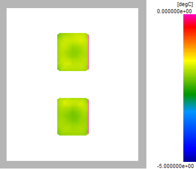
The simulation produces resulting minimum and maximum temperatures of -2.25155 and ‑1.48379respectively, the same as for heat_rota2_xy.pro.
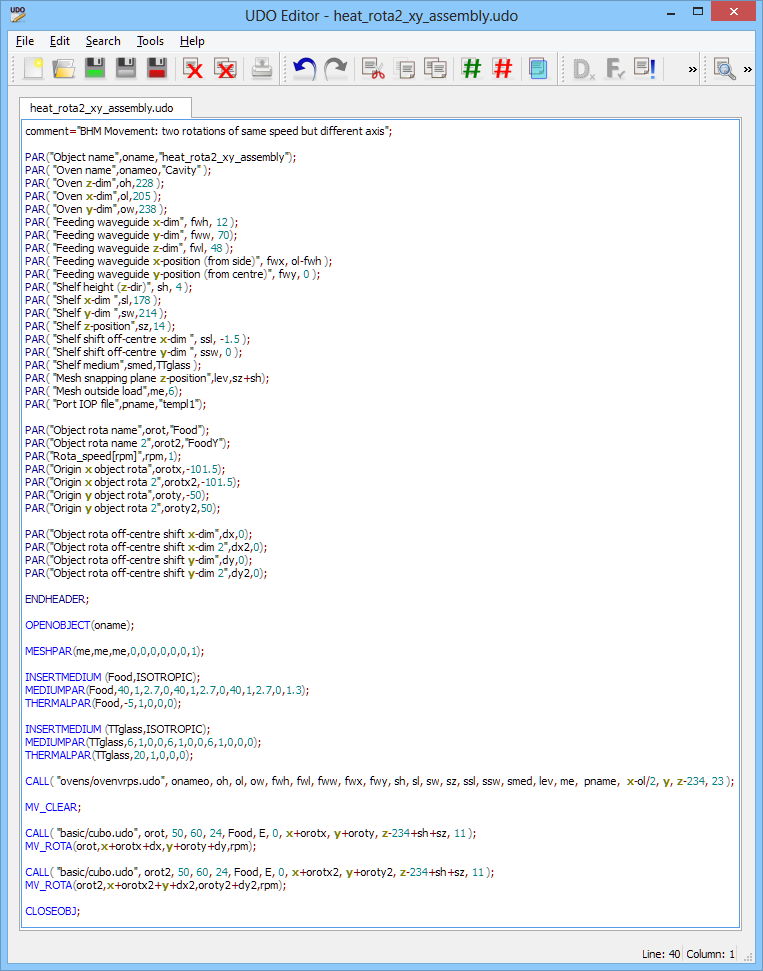
Fig. 7.2-6 Listing of the heat_rota2_xy_assembly.udo script.
|
BHM iter. |
Min temp |
Max temp |
|
|
1 |
-4.97 |
-3.88 |
|
|
2 |
-4.91 |
-2.96 |
|
|
3 |
-4.78 |
-2.50 |
|
|
4 |
-4.62 |
-2.31 |
|
|
5 |
-4.44 |
-2.12 |
|
|
6 |
-4.07 |
-2.01 |
|
|
7 |
-3.79 |
-1.93 |
|
|
8 |
-3.50 |
-1.76 |
|
|
9 |
-3.02 |
-1.69 |
|
|
10 |
-2.81 |
-1.60 |
|
|
11 |
-2.60 |
-1.57 |
|
|
12 |
-2.25 |
-1.48 |
Fig. 7.2-7 Temperature in heat_rota2_xy_assembly project, and final temperature pattern across the load (in -5÷0°C scale, in layer 8).