6.9 Lumped Impedance
The ![]() command from Add section in
command from Add section in ![]() button in Model tab and I/O Ports->Luped Impedances->(Add) Series... command from main menu invoke Lumped Impedance dialogue for adding lumped impedance element with default type set to Series.
button in Model tab and I/O Ports->Luped Impedances->(Add) Series... command from main menu invoke Lumped Impedance dialogue for adding lumped impedance element with default type set to Series.
The ![]() command from Add section in
command from Add section in ![]() button in Model tab and I/O Ports->Luped Impedances->(Add) Parallel... command from main menu invoke Lumped Impedance dialogue for adding lumped impedance element with default type set to Parallel.
button in Model tab and I/O Ports->Luped Impedances->(Add) Parallel... command from main menu invoke Lumped Impedance dialogue for adding lumped impedance element with default type set to Parallel.
The ![]() command from Add section in
command from Add section in ![]() button in Model tab and I/O Ports->Luped Impedances->(Add) Debye... command from main menu invoke Lumped Impedance dialogue for adding lumped impedance element with default type set to Debye.
button in Model tab and I/O Ports->Luped Impedances->(Add) Debye... command from main menu invoke Lumped Impedance dialogue for adding lumped impedance element with default type set to Debye.
The ![]() command from Add section in
command from Add section in ![]() button in Model tab and I/O Ports->Luped Impedances->(Add) Drude... command from main menu invoke Lumped Impedance dialogue for adding lumped impedance element with default type set to Drude.
button in Model tab and I/O Ports->Luped Impedances->(Add) Drude... command from main menu invoke Lumped Impedance dialogue for adding lumped impedance element with default type set to Drude.
The ![]() command from Add section in
command from Add section in ![]() button in Model tab and I/O Ports->Luped Impedances->(Add) Lorentz... command from main menu invoke Lumped Impedance dialogue for adding lumped impedance element with default type set to Lorentz.
button in Model tab and I/O Ports->Luped Impedances->(Add) Lorentz... command from main menu invoke Lumped Impedance dialogue for adding lumped impedance element with default type set to Lorentz.
The ![]() command from Add section in
command from Add section in ![]() button in Model tab and I/O Ports->Luped Impedances->(Add) Lumped... command from main menu invoke Lumped Impedance dialogue for adding lumped impedance element with default settings.
button in Model tab and I/O Ports->Luped Impedances->(Add) Lumped... command from main menu invoke Lumped Impedance dialogue for adding lumped impedance element with default settings.
This dialogue can be also opened for adding or editing the lumped impedance element from Lumped Impedances dialogue.
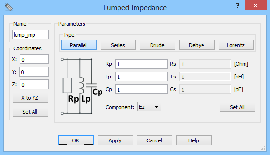
In the Name field the lumped impedance element name, used for identifying the lumped element, should be put.
In the Coordinates frame values of the lumped impedance element position in all three directions should be set. The Set All button allows set the introduced coordinates to all lumped impedances already existing in the project.
In the Parameters frame, the user can independently choose the Type of the lumped circuit. The visualisation of the chosen circuit, indicating the particular p and s parameters available on the right, will appear on the picture. The field Component to which the circuit is connected can be chosen. The Set All button allows set the introduced parameters to all lumped impedances already existed in the project.
It is advised to refer to Lumped impedance element for more information regarding lumped impedance elements.