
1.1.2 Model
QW-Editor Model tab is arranged in sections enabling basic file operations like loading and saving projects, defining basic project settings, drawing geometry from UDO scripts, setting excitation type and its parameters, boundary conditions, meshing, and accessing help for Model commands.
Project section

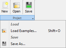
Project section contains the following commands:
![]() - creates new QW-Editor project
- creates new QW-Editor project
![]() - opens QW-Editor project
- opens QW-Editor project
![]() - saves QW-Editor project with the current name
- saves QW-Editor project with the current name
![]() - opens QW-Editor project from QW-Editor examples directory
- opens QW-Editor project from QW-Editor examples directory
![]() - saves QW-Editor project with the new name
- saves QW-Editor project with the new name
Settings section

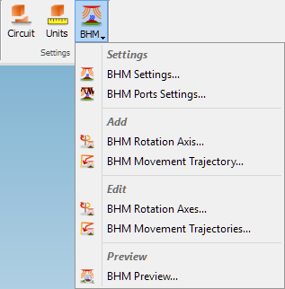
Settings section contains the following commands:
![]() - opens Circuit dialogue with options for circuit properties configuration
- opens Circuit dialogue with options for circuit properties configuration
![]() - opens Units dialogue for specifying the geometry units in which the project will be created, and also the frequency units
- opens Units dialogue for specifying the geometry units in which the project will be created, and also the frequency units
Under ![]() button the following commands are available:
button the following commands are available:
![]() - opens Heating Details dialogue with options for Basic Heating Module process
- opens Heating Details dialogue with options for Basic Heating Module process
![]() - opens BHM Excitation Port Parameters dialogue with options for excitation ports configuration
- opens BHM Excitation Port Parameters dialogue with options for excitation ports configuration
![]() - opens Add BHM Rotation Axis dialogue with options for BHM rotation axis configuration
- opens Add BHM Rotation Axis dialogue with options for BHM rotation axis configuration
![]() - opens Add BHM Movement Trajectory dialogue with options for BHM movement trajectory configuration
- opens Add BHM Movement Trajectory dialogue with options for BHM movement trajectory configuration
![]() - opens BHM Rotation Axes dialogue for managing BHM Rotation Axes
- opens BHM Rotation Axes dialogue for managing BHM Rotation Axes
![]() - opens BHM Movement Trajectories dialogue for managing BHM Movement Trajectories
- opens BHM Movement Trajectories dialogue for managing BHM Movement Trajectories
![]() - opens BHM Preview dialogue for preview of BHM process
- opens BHM Preview dialogue for preview of BHM process
Media section
![]()
Media section contains the following command:
![]() - opens Project Media dialogue that allows managing media in the current project
- opens Project Media dialogue that allows managing media in the current project
UDO section
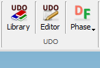
UDO section contains the following commands:
![]() - opens the UDO Library dialogue with UDO scripts
- opens the UDO Library dialogue with UDO scripts
![]() - opens UDO Editor window
- opens UDO Editor window
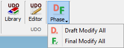
Under ![]() button the following commands are available:
button the following commands are available:
![]() - redraws in draft phase all objects created from UDO scripts (see Biphased Element and Objects chapter for more information)
- redraws in draft phase all objects created from UDO scripts (see Biphased Element and Objects chapter for more information)
![]() - redraws in final phase all objects created from UDO scripts (see Biphased Element and Objects chapter for more information)
- redraws in final phase all objects created from UDO scripts (see Biphased Element and Objects chapter for more information)
Drawing section

Drawing section contains the following commands:
![]() - opens 2D Window displaying the 2D view of 3D structure in a chosen plane and enabling drawing in XY plane
- opens 2D Window displaying the 2D view of 3D structure in a chosen plane and enabling drawing in XY plane
Import/Export section

Import/Export section contains the following commands:
![]() - imports geometry from SAT file with SAT Filter
- imports geometry from SAT file with SAT Filter
![]() - imports geometry from DXF file with DXF Converter
- imports geometry from DXF file with DXF Converter
![]() - exports current geometry to SAT file
- exports current geometry to SAT file
I/O section
![]()
I/O section contains the following command:
![]() - opens I/O Ports Parameters dialogue for setting parameters of all ports defined in the project
- opens I/O Ports Parameters dialogue for setting parameters of all ports defined in the project
Sources and Loads section
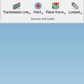
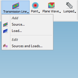
![]() - Transmission Line button contains the following commands:
- Transmission Line button contains the following commands:
![]() - opens Add Transmission Line Port dialogue with options for transmission line source port configuration
- opens Add Transmission Line Port dialogue with options for transmission line source port configuration
![]() - opens Add Transmission Line Port dialogue with options for transmission line load/termination port configuration
- opens Add Transmission Line Port dialogue with options for transmission line load/termination port configuration
![]() - opens Transmission Line Ports dialogue for managing transmission line ports
- opens Transmission Line Ports dialogue for managing transmission line ports
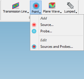
![]() - Point button contains the following commands:
- Point button contains the following commands:
![]() - opens Add Point/Probe dialogue with options for point source configuration
- opens Add Point/Probe dialogue with options for point source configuration
![]() - opens Add Point/Probe dialogue with options for point probe configuration
- opens Add Point/Probe dialogue with options for point probe configuration
![]() - opens Point Sources or Probes dialogue for managing point ports
- opens Point Sources or Probes dialogue for managing point ports
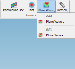
![]() - Plane Wave button contains the following commands:
- Plane Wave button contains the following commands:
![]() - opens Add Plane Wave dialogue with options for plane wave box excitation configuration
- opens Add Plane Wave dialogue with options for plane wave box excitation configuration
![]() - opens Plane Waves dialogue for managing plane wave box excitations
- opens Plane Waves dialogue for managing plane wave box excitations
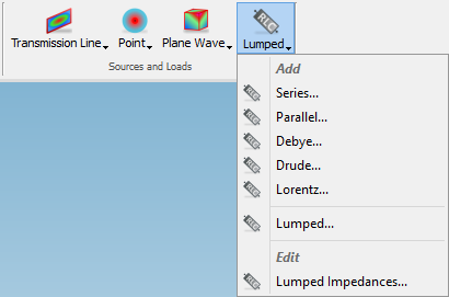
![]() - Lumped button contains the following commands:
- Lumped button contains the following commands:
![]() - opens Add Lumped Impedance dialogue with options for lumped impedance (Series circuit as default) configuration
- opens Add Lumped Impedance dialogue with options for lumped impedance (Series circuit as default) configuration
![]() - opens Add Lumped Impedance dialogue with options for lumped impedance (Parallel circuit as default) configuration
- opens Add Lumped Impedance dialogue with options for lumped impedance (Parallel circuit as default) configuration
![]() - opens Add Lumped Impedance dialogue with options for lumped impedance (Debye circuit as default) configuration
- opens Add Lumped Impedance dialogue with options for lumped impedance (Debye circuit as default) configuration
![]() - opens Add Lumped Impedance dialogue with options for lumped impedance (Drude circuit as default) configuration
- opens Add Lumped Impedance dialogue with options for lumped impedance (Drude circuit as default) configuration
![]() - opens Add Lumped Impedance dialogue with options for lumped impedance (Lorentz circuit as default) configuration
- opens Add Lumped Impedance dialogue with options for lumped impedance (Lorentz circuit as default) configuration
![]() - opens Add Lumped Impedance dialogue with default configuration options for lumped impedance
- opens Add Lumped Impedance dialogue with default configuration options for lumped impedance
![]() - opens Lumped Impedances dialogue for managing lumped impedances
- opens Lumped Impedances dialogue for managing lumped impedances
ABC section
![]()
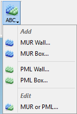
![]() - ABC (Absorbing Boundary Conditions) button contains the following commands:
- ABC (Absorbing Boundary Conditions) button contains the following commands:
![]() - opens Add ABC Wall dialogue with configuration options for a single wall of Mur with superabsorption (MUR) boundary conditions
- opens Add ABC Wall dialogue with configuration options for a single wall of Mur with superabsorption (MUR) boundary conditions
![]() - opens Add ABC Box dialogue with configuration options for a six wall box of Mur with superabsorption (MUR) boundary conditions
- opens Add ABC Box dialogue with configuration options for a six wall box of Mur with superabsorption (MUR) boundary conditions
![]() - opens Add ABC Wall dialogue with configuration options for a single wall of Perfectly Matched Layer (PML) boundary conditions
- opens Add ABC Wall dialogue with configuration options for a single wall of Perfectly Matched Layer (PML) boundary conditions
![]() - opens Add ABC Box dialogue with options for a six wall box of Perfectly Matched Layer (PML) boundary conditions
- opens Add ABC Box dialogue with options for a six wall box of Perfectly Matched Layer (PML) boundary conditions
![]() - opens ABCs dialogue for managing ABCs
- opens ABCs dialogue for managing ABCs
NTF section
![]()
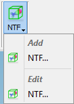
![]() - NTF button contains the following commands:
- NTF button contains the following commands:
![]() - opens Add NTF Box dialogue with options for Near To Far (NTF) Box configuration
- opens Add NTF Box dialogue with options for Near To Far (NTF) Box configuration
![]() - opens Near To Far dialogue for managing NTF boxes
- opens Near To Far dialogue for managing NTF boxes
NTN section
![]()
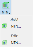
![]() - NTF button contains the following commands:
- NTF button contains the following commands:
![]() - opens Add NTN Box dialogue with options for Near To Near (NTN) Box configuration
- opens Add NTN Box dialogue with options for Near To Near (NTN) Box configuration
![]() - opens Near To Near dialogue for managing NTF boxes
- opens Near To Near dialogue for managing NTF boxes
Monitor section

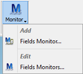
![]() - Monitor button contains the following commands:
- Monitor button contains the following commands:
![]() - opens Add Fields Monitor dialogue with options for Fields Monitor configuration
- opens Add Fields Monitor dialogue with options for Fields Monitor configuration
![]() - opens Fields Monitors dialogue for managing Fields Monitors
- opens Fields Monitors dialogue for managing Fields Monitors
FDTD Mesh section

FDTD Mesh section contains the following commands:
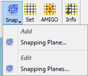
![]() - Snap button contains the following commands:
- Snap button contains the following commands:
![]() - opens Add Snapping Plane dialogue with options for mesh snapping plane configuration
- opens Add Snapping Plane dialogue with options for mesh snapping plane configuration
![]() - opens Snapping Planes dialogue for managing mesh snapping planes
- opens Snapping Planes dialogue for managing mesh snapping planes
![]() - opens Mesh Parameters dialogue with options for FDTD mesh configuration
- opens Mesh Parameters dialogue with options for FDTD mesh configuration
![]() - opens Amigo dialogue with options for automatic FDTD mesh generation configuration
- opens Amigo dialogue with options for automatic FDTD mesh generation configuration
![]() - opens Mesh Info dialogue with information about FDTD mesh
- opens Mesh Info dialogue with information about FDTD mesh
Help section
![]()
Help section contains the following command:
![]() - opens help for Model commands (present chapter)
- opens help for Model commands (present chapter)