2.12.3 Join operations on combined elements
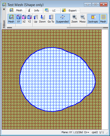
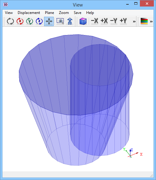
Let us consider an example of a structure composed of a cone and a cylinder intersecting each other, made of the same medium (see example ..\Various\Joinex\cpol1.pro). Two elements (a regular and a combined one) are not joined together. Let us try to check the mesh for this example using File->Export & Run->Export & Test command from main menu or ![]() button from simulation tab of QW-Editor. Fig. 2.12.3-1 presents the structure as seen in QW-Editor as well as one of the intermediate layers of the FDTD cells as seen in the Test Mesh window. The software has meshed the structure correctly. It has assumed that at the time of meshing the Join operation needs to be performed at each cell level.
button from simulation tab of QW-Editor. Fig. 2.12.3-1 presents the structure as seen in QW-Editor as well as one of the intermediate layers of the FDTD cells as seen in the Test Mesh window. The software has meshed the structure correctly. It has assumed that at the time of meshing the Join operation needs to be performed at each cell level.
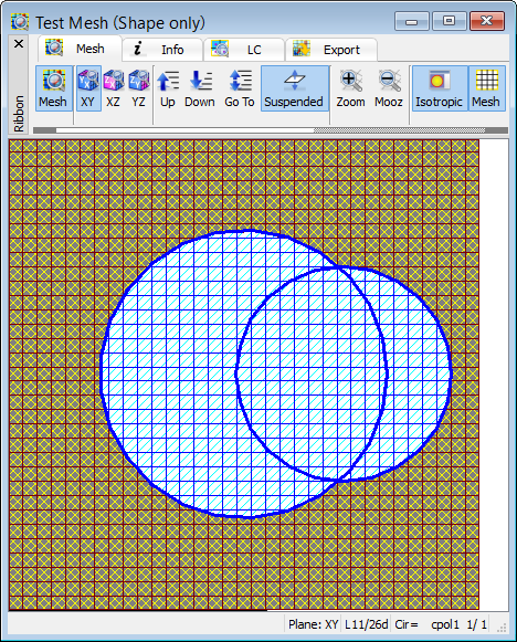
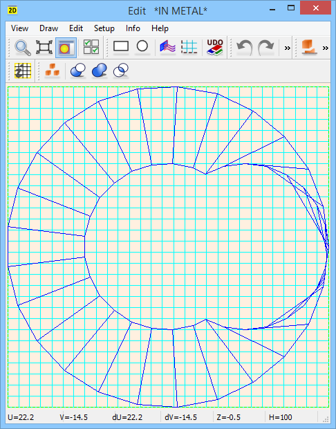
Let us now try to perform the Join operation explicitly in QW-Editor. We mark the cone as Active, cylinder as Passive and execute Glue operation. The result is seen on the left hand side of Fig. 2.12.3-2. The software treats both elements as combined ones and performs the Join operation at the upper and lower levels (at the bottom and the cover). Then it tries to draw links between the consecutive points of the new bottom and the new cover. As a result the meshing at intermediate level is not fully correct as seen on the right hand side of Fig. 2.12.3-2. This brings an important conclusion about performing logical Join operations on combined elements. In general, the joint operations on combined elements can bring inaccurate or even erroneous results due to ambiguity of paths of links between the consecutive points of the bottom and cover contours. Thus there are two basic rules of choosing if the Join operations on combined should be performed:
· When we have intersecting combined elements of the same material, we should not perform the Join operations at all.
· When we cannot avoid Join operations on combined elements (like in the case of intersecting elements of different materials) we should use biphased elements. For such elements, the Boolean operations are performed separately on each layer of FDTD cells. Even if there are possible ambiguities of links between points of adjacent cell layers, they do not influence the actual meshing and shape approximation by QW-3D conformal cells. We should however take into account that biphased elements actually generate separate elements for each cell layer, which increases memory occupied by QW-Editor and decreases the speed of its operation (especially drawing of structure images).

![]()
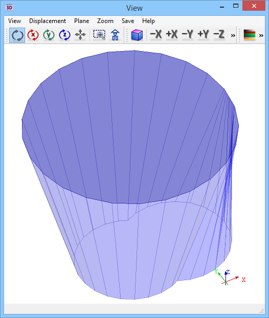
![]() Fig. 2.12.3-1 Illustration of example cpol1.pro.
Fig. 2.12.3-1 Illustration of example cpol1.pro.
![]()