5.4 Lumped Impedance
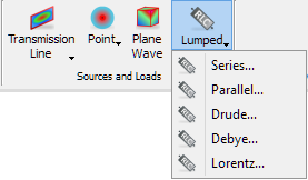
The Lumped button ![]() in the Model tab allows introducing lumped impedance to the considered structure. Under the Lumped drop-down button five circuits are available: Series, Parallel, Drude, Debye, and Lorentz. After choosing one of them the Create Lumped Impedance dialogue appears. The dialogue below shows the parameters for Series circuit option.
in the Model tab allows introducing lumped impedance to the considered structure. Under the Lumped drop-down button five circuits are available: Series, Parallel, Drude, Debye, and Lorentz. After choosing one of them the Create Lumped Impedance dialogue appears. The dialogue below shows the parameters for Series circuit option.

In the Name field the lumped impedance element name, used for identifying the lumped element, should be put.
In the Coordinates frame values of the lumped impedance element position in all three directions should be set.
In the Parameters frame, the user can independently choose the Type of the lumped circuit. The visualisation of the chosen circuit, indicating the particular p and s parameters available on the right, will appear on the picture. The field Component to which the circuit is connected can be chosen. The Set All button allows set the introduced parameters to all lumped impedances already existed in the project.
It is advised to refer to Lumped impedance element for more information regarding lumped impedance elements.
Python code
The python code, which can be useful when creating project scripts, generated by Create Lumped Impedance dialogue for default parameters:
from FreeCAD import Base
QW_Modeller.addQWObject("QW_Modeller::LumpedPointPort","LumpedImp")
App.ActiveDocument.LumpedImp.Placement = Base.Placement(Base.Vector(0.00000,0.00000,0.00000),Base.Rotation(0.00000,0.00000,0.00000,1.00000))
App.ActiveDocument.LumpedImp.Type = "Series"
App.ActiveDocument.LumpedImp.Component = "Ex"
App.ActiveDocument.LumpedImp.Rp = 1.00000
App.ActiveDocument.LumpedImp.Lp = 1.00000
App.ActiveDocument.LumpedImp.Cp = 1.00000
App.ActiveDocument.LumpedImp.Rs = 1.00000
App.ActiveDocument.LumpedImp.Ls = 1.00000
App.ActiveDocument.LumpedImp.Cs = 1.00000
Gui.ActiveDocument.LumpedImp.ShowText = True
Gui.ActiveDocument.LumpedImp.TextSize = 14
App.ActiveDocument.recompute()
Gui.SendMsgToActiveView("ViewFit")