
1.1.5 Model
QW-Modeller Model tab is organised in twelve sections, which allow defining basic project settings, excitation type and its parameters, boundary conditions, and meshing.
Project section
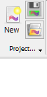
Project section contains the following commands:
![]() - creates new QW-Modeller project. See New Project chapter for more information.
- creates new QW-Modeller project. See New Project chapter for more information.
![]() - saves QW-Modeller project with the current name (if the project has not been saved yet, the Save QW-Modeller Project dialogue will appear).
- saves QW-Modeller project with the current name (if the project has not been saved yet, the Save QW-Modeller Project dialogue will appear).
![]() - opens QW-Modeller (or other supported format) project.
- opens QW-Modeller (or other supported format) project.
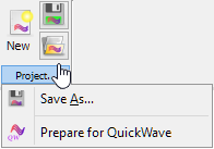
![]() - opens Save QW-Modeller Project dialogue for introducing project file name.
- opens Save QW-Modeller Project dialogue for introducing project file name.
![]() - constructs QuickWave components tree in the Tree View.
- constructs QuickWave components tree in the Tree View.
See Supported formats chapter for more information.
Edit section


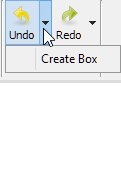

Edit section contains the following commands:
![]() - undo operation
- undo operation
![]() - redo operation
- redo operation
![]() - copy selected object(s)
- copy selected object(s)
![]() - paste copied object(s)
- paste copied object(s)
![]() - duplicate selected object(s)
- duplicate selected object(s)
![]() - select all objects
- select all objects
![]() - box selection in the 3D view
- box selection in the 3D view
Settings section

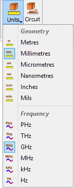
Settings section contains the following commands:
![]() - specifies the geometry units in which the project will be created and also the frequency units. See Units chapter for more information.
- specifies the geometry units in which the project will be created and also the frequency units. See Units chapter for more information.
![]() - opens Circuit Settings dialogue with options for circuit properties configuration. See Circuit Settings chapter for more information.
- opens Circuit Settings dialogue with options for circuit properties configuration. See Circuit Settings chapter for more information.
BHM section

BHM section contains the following commands:
![]() - opens Heating Details dialogue with parameters of Basic Heating Module. See Heating Details chapter for more information.
- opens Heating Details dialogue with parameters of Basic Heating Module. See Heating Details chapter for more information.
![]() - opens BHM Excitation Port Parameters dialogue for configuring options for excitation ports configuration. See Excitation Port Parameters chapter for more information.
- opens BHM Excitation Port Parameters dialogue for configuring options for excitation ports configuration. See Excitation Port Parameters chapter for more information.
![]() - opens Components dialogue for choosing the additional components and quantities that will be saved by QW-Simulator after each BHM step. See Components chapter for more information.
- opens Components dialogue for choosing the additional components and quantities that will be saved by QW-Simulator after each BHM step. See Components chapter for more information.
![]() - opens BHM Rotation Axis dialogue for adding BHM rotation axis. See BHM Rotation Axis chapter for more information.
- opens BHM Rotation Axis dialogue for adding BHM rotation axis. See BHM Rotation Axis chapter for more information.
![]() - opens BHM Movement Trajectory dialogue for adding BHM movement trajectory. See BHM Movement Trajectory chapter for more information.
- opens BHM Movement Trajectory dialogue for adding BHM movement trajectory. See BHM Movement Trajectory chapter for more information.
![]() - opens BHM Preview dialogue for preview of BHM movement process. See Preview chapter for more information.
- opens BHM Preview dialogue for preview of BHM movement process. See Preview chapter for more information.
![]() - switches to BHM tab of QW-Modeller Ribbon
- switches to BHM tab of QW-Modeller Ribbon
Sources and Loads section


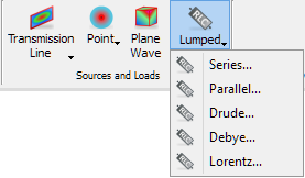
Sources and Loads section contains the following commands:
![]() - opens Create Transmission Line Source dialogue with options for transmission line source port configuration. See Transmission Line Port chapter for more information.
- opens Create Transmission Line Source dialogue with options for transmission line source port configuration. See Transmission Line Port chapter for more information.
![]() - opens Create Transmission Line Load dialogue with options for transmission line load port configuration. See Transmission Line Port chapter for more information.
- opens Create Transmission Line Load dialogue with options for transmission line load port configuration. See Transmission Line Port chapter for more information.
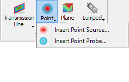
![]() - opens Create Point Source dialogue with options for point port configuration. See Point Port chapter for more information.
- opens Create Point Source dialogue with options for point port configuration. See Point Port chapter for more information.
![]() - opens Create Point Probe dialogue with options for point probe configuration. See Point Port chapter for more information.
- opens Create Point Probe dialogue with options for point probe configuration. See Point Port chapter for more information.
![]() - opens Create Plane Wave Box dialogue with options for plane wave configuration. See Plane Wave Box chapter for more information.
- opens Create Plane Wave Box dialogue with options for plane wave configuration. See Plane Wave Box chapter for more information.
![]() - opens Create Lumped Impedance dialogue with options for lumped impedance (Series circuit as default) configuration. See Lumped Impedance chapter for more information.
- opens Create Lumped Impedance dialogue with options for lumped impedance (Series circuit as default) configuration. See Lumped Impedance chapter for more information.
![]() - opens Create Lumped Impedance dialogue with options for lumped impedance (Parallel circuit as default) configuration. See Lumped Impedance chapter for more information.
- opens Create Lumped Impedance dialogue with options for lumped impedance (Parallel circuit as default) configuration. See Lumped Impedance chapter for more information.
![]() - opens Create Lumped Impedance dialogue with options for lumped impedance (Drude circuit as default) configuration. See Lumped Impedance chapter for more information.
- opens Create Lumped Impedance dialogue with options for lumped impedance (Drude circuit as default) configuration. See Lumped Impedance chapter for more information.
![]() - opens Create Lumped Impedance dialogue with options for lumped impedance (Debye circuit as default) configuration. See Lumped Impedance chapter for more information.
- opens Create Lumped Impedance dialogue with options for lumped impedance (Debye circuit as default) configuration. See Lumped Impedance chapter for more information.
![]() - opens Create Lumped Impedance dialogue with options for lumped impedance (Lorentz circuit as default) configuration. See Lumped Impedance chapter for more information.
- opens Create Lumped Impedance dialogue with options for lumped impedance (Lorentz circuit as default) configuration. See Lumped Impedance chapter for more information.
Wire section
![]()
Wire section contains the following commands:
![]() - opens Create Wire dialogue with options for wire configuration. See Wire chapter for more information.
- opens Create Wire dialogue with options for wire configuration. See Wire chapter for more information.
ABC section
![]()
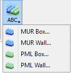
ABC (Absorbing Boundary Conditions) section contains the following commands:
![]() - opens Create MUR Box dialogue with options for Mur with superabsorption (MUR) configuration. See Absorbing Box chapter for more information.
- opens Create MUR Box dialogue with options for Mur with superabsorption (MUR) configuration. See Absorbing Box chapter for more information.
![]() - opens Create MUR Wall dialogue with options for Mur with superabsorption (MUR) configuration. See Absorbing Wall chapter for more information.
- opens Create MUR Wall dialogue with options for Mur with superabsorption (MUR) configuration. See Absorbing Wall chapter for more information.
![]() - opens Create PML Box dialogue with options for Perfectly Matched Layer (PML) configuration. See Absorbing Box chapter for more information.
- opens Create PML Box dialogue with options for Perfectly Matched Layer (PML) configuration. See Absorbing Box chapter for more information.
![]() - opens Create PML Wall dialogue with options for Perfectly Matched Layer (PML) configuration. See Absorbing Wall chapter for more information.
- opens Create PML Wall dialogue with options for Perfectly Matched Layer (PML) configuration. See Absorbing Wall chapter for more information.
NTF section
![]()
NTF section contains the following commands:
![]() - opens Create NTF Box dialogue with options for Near To Far Box (NTF) configuration. See NTF Box chapter for more information.
- opens Create NTF Box dialogue with options for Near To Far Box (NTF) configuration. See NTF Box chapter for more information.
Monitor section

Monitor section contains the following commands:
![]() - opens Create Field Monitor Box dialogue with options for Field Monitor configuration. See Field Monitor Box chapter for more information.
- opens Create Field Monitor Box dialogue with options for Field Monitor configuration. See Field Monitor Box chapter for more information.
Mesh section
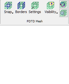


Mesh section contains the following commands:
![]() - opens Create Snapping Plane dialogue with options for mesh snapping planes configuration. See Mesh Snapping Plane chapter for more information.
- opens Create Snapping Plane dialogue with options for mesh snapping planes configuration. See Mesh Snapping Plane chapter for more information.
![]() - opens Create Mesh Box dialogue with options for mesh box configuration. See Mesh Box chapter for more information.
- opens Create Mesh Box dialogue with options for mesh box configuration. See Mesh Box chapter for more information.
![]() - opens Boundary Conditions dialogue with options for project boundaries configuration. See Borders chapter for more information.
- opens Boundary Conditions dialogue with options for project boundaries configuration. See Borders chapter for more information.
![]() - opens Mesh Settings dialogue with options for FDTD mesh configuration. See Mesh Settings chapter for more information.
- opens Mesh Settings dialogue with options for FDTD mesh configuration. See Mesh Settings chapter for more information.
![]() - recalculates FDTD mesh
- recalculates FDTD mesh
![]() - opens Mesh Inspect dialogue with FDTD mesh information. See Mesh Inspect chapter for more information.
- opens Mesh Inspect dialogue with FDTD mesh information. See Mesh Inspect chapter for more information.
The ![]() button contains the following commands:
button contains the following commands:
![]() - shows/hides FDTD mesh in X direction
- shows/hides FDTD mesh in X direction
![]() - shows/hides FDTD mesh in Y direction
- shows/hides FDTD mesh in Y direction
![]() - shows/hides FDTD mesh in Z direction
- shows/hides FDTD mesh in Z direction
![]() - shows/hides FDTD mesh
- shows/hides FDTD mesh
![]() - shows/hides electric FDTD mesh
- shows/hides electric FDTD mesh
![]() - shows/hides magnetic FDTD mesh
- shows/hides magnetic FDTD mesh
![]() - shows/hides FDTD mesh in a box form
- shows/hides FDTD mesh in a box form
![]() - shows/hides FDTD mesh in a short lines form
- shows/hides FDTD mesh in a short lines form
![]() - shows/hides FDTD mesh boundary conditions. See Borders chapter for more information.
- shows/hides FDTD mesh boundary conditions. See Borders chapter for more information.
See also FDTD Mesh chapter for more information.
Parameters section

Parameters section contains the following commands:
![]() - opens QW-Parameters dock window that allows defining user variables
- opens QW-Parameters dock window that allows defining user variables
Simulation section

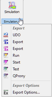
Simulation section contains the following commands:
![]() - switches to Simulation tab of QW-Modeller Ribbon
- switches to Simulation tab of QW-Modeller Ribbon
![]() - exports current project to UDO file
- exports current project to UDO file
![]() - exports current project to UDO file, run QW-Editor and create QW-Editor project (*.pro) from the exported UDO
- exports current project to UDO file, run QW-Editor and create QW-Editor project (*.pro) from the exported UDO
![]() - exports current project to UDO file, run QW-Editor, create QW-Editor project (*.pro) from the exported UDO and export the project to QW-Simulator
- exports current project to UDO file, run QW-Editor, create QW-Editor project (*.pro) from the exported UDO and export the project to QW-Simulator
![]() - exports current project to UDO file, run QW-Editor, create QW-Editor project (*.pro) from the exported UDO, export the project to QW-Simulator and run QW-Simulator
- exports current project to UDO file, run QW-Editor, create QW-Editor project (*.pro) from the exported UDO, export the project to QW-Simulator and run QW-Simulator
![]() - exports current project to UDO file, run QW-Editor, create QW-Editor project (*.pro) from the exported UDO, export the project to QW-Simulator, run QW-Simulator and start simulation
- exports current project to UDO file, run QW-Editor, create QW-Editor project (*.pro) from the exported UDO, export the project to QW-Simulator, run QW-Simulator and start simulation
![]() - exports current project to UDO file, run QW-Editor, create QW-Editor project (*.pro) from the exported UDO, export the project to QW-Simulator, run QW-Simulator and open Test Mesh window
- exports current project to UDO file, run QW-Editor, create QW-Editor project (*.pro) from the exported UDO, export the project to QW-Simulator, run QW-Simulator and open Test Mesh window
![]() - exports current project to UDO file, run QW-Editor, create QW-Editor project (*.pro) from the exported UDO, export the project to QW-Simulator, run QW-Simulator and start simulation using QProny module
- exports current project to UDO file, run QW-Editor, create QW-Editor project (*.pro) from the exported UDO, export the project to QW-Simulator, run QW-Simulator and start simulation using QProny module
![]() - opens Export Options dialogue with options for export action configuration. See Export Options chapter for more information.
- opens Export Options dialogue with options for export action configuration. See Export Options chapter for more information.
Help section
![]()
Help section contains the following command:
![]() - opens help for Model commands (present chapter)
- opens help for Model commands (present chapter)