5.5 Wire
![]()
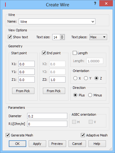
The Wire button ![]() available in the Model tab allows introducing thin wires (of radius less than a cell size) parallel to any of the coordinate system axes. After pressing Wire button the Create Wire dialogue appears. The wire starts at Start point and ends at End point defined either with X,Y,Z coordinates or simply by setting the wire’s length. The orientation of the wire is set using Orientation option and the direction of the wire (from Start point) can be defined using Direction option. Adaptive Mesh option automatically adapts FDTD mesh around the wire to ensure the proper cell size in the wire’s neighbourhood (radius of the wire should be less than a cell size). Connection between wires can be easily done by selecting start/end point of previously defined wire (see Selecting Objects for more information) and using From Pick option for currently drawn wire.
available in the Model tab allows introducing thin wires (of radius less than a cell size) parallel to any of the coordinate system axes. After pressing Wire button the Create Wire dialogue appears. The wire starts at Start point and ends at End point defined either with X,Y,Z coordinates or simply by setting the wire’s length. The orientation of the wire is set using Orientation option and the direction of the wire (from Start point) can be defined using Direction option. Adaptive Mesh option automatically adapts FDTD mesh around the wire to ensure the proper cell size in the wire’s neighbourhood (radius of the wire should be less than a cell size). Connection between wires can be easily done by selecting start/end point of previously defined wire (see Selecting Objects for more information) and using From Pick option for currently drawn wire.
Python code
The python code, which can be useful when creating project scripts, generated by Create Wire dialogue for default parameters:
from FreeCAD import Base
QW_Modeller.addQWObject("QW_Modeller::Wire","Wire")
App.ActiveDocument.Wire.Placement = Base.Placement(Base.Vector(0.00000,0.00000,0.00000),Base.Rotation(0.00000,0.00000,0.00000,1.00000))
App.ActiveDocument.Wire.Orientation = "Z"
App.ActiveDocument.Wire.X1 = 0.00000
App.ActiveDocument.Wire.Y1 = 0.00000
App.ActiveDocument.Wire.Z1 = 0.00000
App.ActiveDocument.Wire.X2 = 0.00000
App.ActiveDocument.Wire.Y2 = 0.00000
App.ActiveDocument.Wire.Z2 = 1.00000
App.ActiveDocument.Wire.Length = 1.00000
App.ActiveDocument.Wire.Resistance = 0.00000
App.ActiveDocument.Wire.Diameter = 0.20000
App.ActiveDocument.Wire.OrientationH = False
App.ActiveDocument.Wire.OrientationV = False
App.ActiveDocument.Wire.AdaptiveMesh = True
Gui.ActiveDocument.Wire.ShowText = True
Gui.ActiveDocument.Wire.TextSize = 14
Gui.ActiveDocument.Wire.TextPlace = 1
App.ActiveDocument.recompute()
Gui.SendMsgToActiveView("ViewFit")