5.7 Absorbing Wall
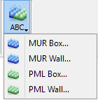
The ![]() command from the drop-dowm menu under
command from the drop-dowm menu under ![]() button in the Model tab and Model->Absorbing Boundary Conditions->MUR Wall... command from main menu invoke ABC Wall dialogue for adding abc wall with default settings for MUR.
button in the Model tab and Model->Absorbing Boundary Conditions->MUR Wall... command from main menu invoke ABC Wall dialogue for adding abc wall with default settings for MUR.
The ![]() command from the drop-dowm menu under
command from the drop-dowm menu under ![]() button in the Model tab and Model->Absorbing Boundary Conditions->PML Wall... command from main menu invoke ABC Wall dialogue for adding abc wall with default settings for PML.
button in the Model tab and Model->Absorbing Boundary Conditions->PML Wall... command from main menu invoke ABC Wall dialogue for adding abc wall with default settings for PML.
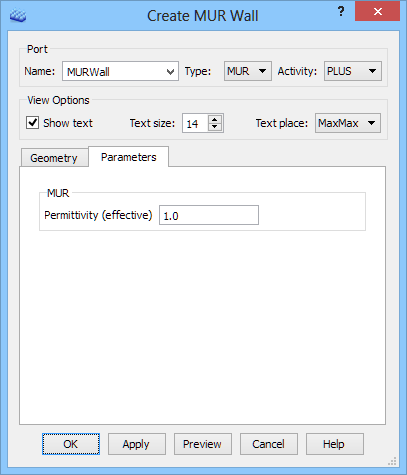
When choosing MUR Wall option the Create MUR Wall dialogue appears.

The wall name in the Name field can be set and the type of an absorbing wall can be chosen in the Type drop-down list. Activity drop-down list allows choosing the wall activity (Plus or Minus), which depends on the wall’s position with respect to the considered structure.
The View Options frame allows deciding if the MUR Wall should be signed in the project window (Show text), choosing the Text size and Text place (at which box’s corner it should be placed).
In the Geometry tab the user sets the wall Orientation by choosing an appropriate axis. In the Position frame the position and dimensions of the wall are set. There are two options available in this manner. First one, the user puts all data manually. To set the port position the Use position option needs to be checked and the position is defined explicitly. The in plane dimensions of the wall can be set in three ways. Full Plane option sets the wall dimensions equal to the bounding dimensions of the entire project in the directions perpendicular to the wall orientation. Coordinates option allows introducing MinMax coordinates between which the wall will be created/stretched out. Dimensions option allows defining wall dimensions explicitly but requires also Min coordinates indicating where the wall geometry starts.
The second option allows defining the port position and dimensions by indicating the element at which it should be created. The From Pick option causes that the port is placed at a bounding box of the selected element (e.g. at a plane, between selected edges or points). To use this option the user needs to firstly select the element in the project window and then press From Pick button.
In the Parameters tab the parameters for the absorbing wall. Absorbing wall of MUR type needs the effective permittivity of the medium in which the wave propagates. It is used by the software to calculate the correct phase velocity of the wave. Incorrect assumption of the effective permittivity increases the level of spurious reflections from the ABC. By default it is assumed that the medium is air and the effective permittivity value is set to 1.
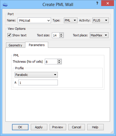
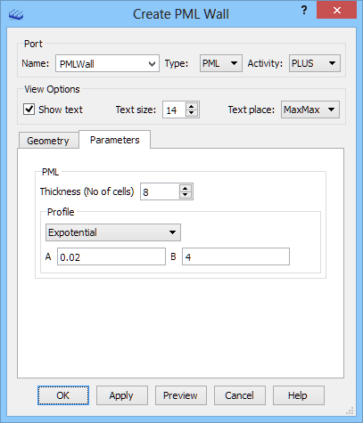
Absorbing wall of PML type needs to specify the PML thickness (in the number of cells) and to select the conductivity profile from the following:
· Parabolic (used in most usual applications) - its conductivity varies as: A*x^2, where x=(distance from PML edge)/(PML thickness) and A set in the dialogue,
· Exponential - its conductivity varies as: A*exp(B*x) with x defined as above, and A, B set in the dialogue.
It is advised to refer to Absorbing Boundary Conditions for more information regarding both types of absorbing boundary conditions.
Python code
The python code, which can be useful when creating project scripts, generated by Create MUR Wall and Create PML Wall dialogue for default parameters:
MUR Wall
from FreeCAD import Base
QW_Modeller.addQWObject("QW_Modeller::AbsorbingWall","MURWall")
App.ActiveDocument.MURWall.Orientation = "X"
App.ActiveDocument.MURWall.Length = 10.00000
App.ActiveDocument.MURWall.Width = 10.00000
App.ActiveDocument.MURWall.Placement = Base.Placement(Base.Vector(0.00000,5.00000,5.00000),Base.Rotation(0.50000,0.50000,0.50000,0.50000))
App.ActiveDocument.MURWall.Position = 0.00000
App.ActiveDocument.MURWall.Activity = "PLUS"
Gui.ActiveDocument.MURWall.AbsorberDepth = 2.50000
Gui.ActiveDocument.MURWall.ShowText = True
Gui.ActiveDocument.MURWall.TextSize = 14
Gui.ActiveDocument.MURWall.TextPlace = 3
App.ActiveDocument.MURWall.Type = "MUR"
App.ActiveDocument.MURWall.EffectivePermittivity = 1.00000
App.ActiveDocument.recompute()
Gui.SendMsgToActiveView("ViewFit")
PML Wall (Parabolic)
from FreeCAD import Base
QW_Modeller.addQWObject("QW_Modeller::AbsorbingWall","PMLWall")
App.ActiveDocument.PMLWall.Orientation = "X"
App.ActiveDocument.PMLWall.Length = 10.00000
App.ActiveDocument.PMLWall.Width = 10.00000
App.ActiveDocument.PMLWall.Placement = Base.Placement(Base.Vector(0.00000,5.00000,5.00000),Base.Rotation(0.50000,0.50000,0.50000,0.50000))
App.ActiveDocument.PMLWall.Position = 0.00000
App.ActiveDocument.PMLWall.Activity = "PLUS"
Gui.ActiveDocument.PMLWall.AbsorberDepth = 2.50000
Gui.ActiveDocument.PMLWall.ShowText = True
Gui.ActiveDocument.PMLWall.TextSize = 14
Gui.ActiveDocument.PMLWall.TextPlace = 3
App.ActiveDocument.PMLWall.Type = "PML"
App.ActiveDocument.PMLWall.PMLProfile = "Parabolic"
App.ActiveDocument.PMLWall.Thickness = 8
App.ActiveDocument.PMLWall.ParabolicA = 1.00000
App.ActiveDocument.recompute()
Gui.SendMsgToActiveView("ViewFit")
PML Wall (Expotential)
from FreeCAD import Base
QW_Modeller.addQWObject("QW_Modeller::AbsorbingWall","PMLWall")
App.ActiveDocument.PMLWall.Orientation = "X"
App.ActiveDocument.PMLWall.Length = 10.00000
App.ActiveDocument.PMLWall.Width = 10.00000
App.ActiveDocument.PMLWall.Placement = Base.Placement(Base.Vector(0.00000,5.00000,5.00000),Base.Rotation(0.50000,0.50000,0.50000,0.50000))
App.ActiveDocument.PMLWall.Position = 0.00000
App.ActiveDocument.PMLWall.Activity = "PLUS"
Gui.ActiveDocument.PMLWall.AbsorberDepth = 2.50000
Gui.ActiveDocument.PMLWall.ShowText = True
Gui.ActiveDocument.PMLWall.TextSize = 14
Gui.ActiveDocument.PMLWall.TextPlace = 3
App.ActiveDocument.PMLWall.Type = "PML"
App.ActiveDocument.PMLWall.PMLProfile = "Expotential"
App.ActiveDocument.PMLWall.Thickness = 8
App.ActiveDocument.PMLWall.ExpotentialA = 0.02000
App.ActiveDocument.PMLWall.ExpotentialB = 4.00000
App.ActiveDocument.recompute()
Gui.SendMsgToActiveView("ViewFit")