


© 2017 QWED Company. All rights reserved. 2017 | Home | Events | Products | Applications | Projects | About | Support | Log In
SOFTWARE PRODUCTS
HARDWARE PRODUCTS
APPLICATIONS
ABOUT
SUPPORT


Version 2.0 upd
Appendix to Version2.0: Temporary instructions for running QW software (QW-3D and QW-V2D), version 2.0, with asymptotic boundary conditions
1. Introductory remarks
Asymptotic boundary conditions (ASBC) are a new feature of QW software, included in version 2.0 following the suggestion of our users.
Regarding the orientation and geometry of ASBC, the following restrictions apply in version 2.0 of QW software:
• ASBC can only be defined in planes perpendicular to one of the coordinate axis (Ox, Oy, Oz in QW-3D; Ox, Or, Oj in QW-V2D),
• in "vertical" planes (parallel to xz, yz in QW-3D; xj , rj in QW-V2D) ASBC must have a rectangular shape;
• in "horizontal" planes (parallel to xy in QW-3D) arbitrarily-shaped ASBC can be defined, but a stair-case approximation will be made.
The above restrictions can be reconsidered in version 2.1 or later, based of the users feedback.
2. Assumed definition of asymptotic boundary conditions
ASBC are defined by setting to zero one of the electric field components over the region covered by ASBC. The correspondence between the choice of this field component and the terminology of QW-Editor is specified by the tables below:
Table 1: ASBC in QW-3D


discover accurate EM modelling
| ASBC parallel to plane: | ASBC orientation: | ASBC definition: |
| xy | horizontal (h) | Ex==0; |
| xy | vertical (v) | Ey==0; |
| xz | horizontal (h) | Ex==0; |
| xz | vertical (v) | Ez==0; |
| yz | horizontal (h) | Ey==0; |
| yz | vertical (v) | Ez==0; |
| ASBC parallel to plane: | ASBC orientation: | ASBC definition: |
| xr | horizontal (h) | Ex==0; |
| xr | vertical (v) | Er==0; |
| xj | horizontal (h) | Ex==0; |
| xj | vertical (v) | Ej==0; |
| rj | horizontal (h) | Er==0; |
| rj | vertical (v) | Ej==0; |
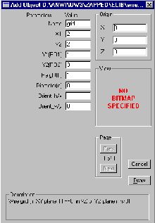
Pressing Draw creates a rectangular wire grid perpendicular to the x-axis, at x=X1=X2=2, based at level Z=0, with height h=1, between Y1=1 and Y2=3 (all in current project units). The grid will be filled with horizontal (y-oriented - see Table 1) wires. If the FDTD mesh lines are at z=0,1,2,�, the y-oriented wires will appear at z=0,1.
The user can modify the parameters, creating different wire grids. Please note that:
• The grids must be planar (not volumetric). Consequently, we must make one of the three settings: h=0, or X1=X2, or Y1=Y2. Otherwise a warning will appear.
• Orientation boxes allow to choose horizontal and/or vertical wires. Setting Orient_h/x=1 will create horizontal wires, rient_v/y=1 will create vertical wires. If both orientations are set to 1, a 2D mesh of wires will be created - this will no longer imitate ASBC, but rather to a thin metal plate. If none of the orientations is checked, no wires will be created.
• If d>0, all wires in the grid will have diameter d. In such a case, besides setting the tangential E-field components to zero, singularity corrections will be applied to the H-fields encircling the wire, and E-fields perpendicular to the wire.
• The X and Y origin coordinates are irrelevant.
5. Manual definition of xz and yz wire grids in QW-3D
A grid of wires parallel to the xz plane can be created by drawing an x-oriented wire, in a standard way, but of non-zero height. Please note that:
• Default orientation of wires in the grid is horizontal (x-oriented). The uppermost wire will not be created. For example, if the wire element is drawn at level z=0, of height h=5, and the FDTD mesh is at z=0,1,2,3�. - the individual wires will be set only at z=1,2,3,4.
• Wire orientation can be changed to vertical (z-oriented) in the Element Change dialogue (which can be obtained by selecting the wire element on the Select Element list). The vertical wires will be of user-defined height h. However, the last wire on the right will not be created. For example, if the wire element is drawn between x1=1 and x2=3, and the FDTD mesh lines are at x=0,1,2,3�. - the individual vertical wires will be set only at x=1,2.
Analogoous rules apply to wire grids parallel to the yz plane (y replacing x in the above description).
6. Manual definition of xy wire grids in QW-3D
A grid of wires parallel to the xy plane can be created by drawing a metal element of zero height, in a standard way, of arbitrary shape. The Element Change dialogue for such elements has now been supplemented with Advanced parameters part. This allows to choose between a metal patch or wire grid, and to specify orientation and diameter of wires. Please note that:
• If only H or V orientation box is checked, the x- or y-oriented wires are created, respectively. The last wire in the positive x - or y-direction, respectively, is not created.
• If both H and V orientation boxes are checked, a 2D grid of the x- and y-oriented wires is created. Stair-case approximation of the shape is applied. The last wires in the positive x- and y-directions are not created.
• If none of the orientation boxes is checked (default), a thin metal layer is conformally modelled, as in previous versions of the software.
7. Definition of ASBC in QW-V2D with wireg_2dv.udo
Invoking the Draw-Get-LibItem command and selecting wireg_2dv.udo shows the following dialogue with default parameters:
The user can modify the parameters, creating different wire grids. Please note that:
• The grids must be planar (not volumetric). Consequently, we must make one of the three settings: h=0, or X1=X2, or Y1=Y2. Otherwise a warning will appear.
• Orientation boxes allow to choose horizontal and/or vertical wires. Setting Orient_h/x=1 will create horizontal wires, rient_v/y=1 will create vertical wires. If both orientations are set to 1, a 2D mesh of wires will be created - this will no longer imitate ASBC, but rather to a thin metal plate. If none of the orientations is checked, no wires will be created.
• If d>0, all wires in the grid will have diameter d. In such a case, besides setting the tangential E-field components to zero, singularity corrections will be applied to the H-fields encircling the wire, and E-fields perpendicular to the wire.
• The X and Y origin coordinates are irrelevant.
5. Manual definition of xz and yz wire grids in QW-3D
A grid of wires parallel to the xz plane can be created by drawing an x-oriented wire, in a standard way, but of non-zero height. Please note that:
• Default orientation of wires in the grid is horizontal (x-oriented). The uppermost wire will not be created. For example, if the wire element is drawn at level z=0, of height h=5, and the FDTD mesh is at z=0,1,2,3�. - the individual wires will be set only at z=1,2,3,4.
• Wire orientation can be changed to vertical (z-oriented) in the Element Change dialogue (which can be obtained by selecting the wire element on the Select Element list). The vertical wires will be of user-defined height h. However, the last wire on the right will not be created. For example, if the wire element is drawn between x1=1 and x2=3, and the FDTD mesh lines are at x=0,1,2,3�. - the individual vertical wires will be set only at x=1,2.
Analogoous rules apply to wire grids parallel to the yz plane (y replacing x in the above description).
6. Manual definition of xy wire grids in QW-3D
A grid of wires parallel to the xy plane can be created by drawing a metal element of zero height, in a standard way, of arbitrary shape. The Element Change dialogue for such elements has now been supplemented with Advanced parameters part. This allows to choose between a metal patch or wire grid, and to specify orientation and diameter of wires. Please note that:
• If only H or V orientation box is checked, the x- or y-oriented wires are created, respectively. The last wire in the positive x - or y-direction, respectively, is not created.
• If both H and V orientation boxes are checked, a 2D grid of the x- and y-oriented wires is created. Stair-case approximation of the shape is applied. The last wires in the positive x- and y-directions are not created.
• If none of the orientation boxes is checked (default), a thin metal layer is conformally modelled, as in previous versions of the software.
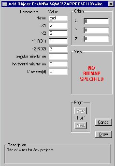
7. Definition of ASBC in QW-V2D with wireg_2dv.udo
Invoking the Draw-Get-LibItem command and selecting wireg_2dv.udo shows the following dialogue with default parameters:
Pressing Draw creates a grid of azimuthal (j-oriented - see Table 2) wires. The grid is perpendicular to the x-axis, located at x=X1=X2=2, between Y1=1 and Y2=3 (all in current project units).
The user can modify the parameters, creating different wire grids. Please note that:
• The grids must be linear in xr plane, parallel to x- or r-axis. Consequently, we must make one of the two settings: X1=X2 or Y1=Y2. Otherwise a warning will appear.
• Orientation boxes allow to choose horizontal and/or vertical wires. Setting Orient_h/x=1 will create horizontal (x- or r-oriented) wires. Although only one wire will be seen on the FDTD mesh, in view of the assumed axial symmetry of the structure, it will model a grid of rotationally repeated wires. Orient_v/y=1 will create vertical (j-oriented) wires. If both orientations are set to 1, a 2D mesh of wires will be created - this will no longer imitate ASBC, but rather to a thin metal plate. If none of the orientations is checked, no wires will be created.
• If d>0, j-oriented wires in the grid will have diameter d. In such a case, besides setting the tangential E-field components to zero, singularity corrections will be applied to the H-fields encircling the wire, and E-fields perpendicular to the wire. The d parameter does not apply to the x- and r-oriented wires.
• The X and Y origin coordinates are irrelevant. The Z coordinate of the origin must not be changed.
8. Manual definition of xr and rj wire grids in QW-V2D
Please note that a single x- or r-oriented wire, drawn in a standard way, naturally corresponds to a grid of rotationally repeated wires, due to the assumed axial symmetry of the structure.
By entering the Element Change dialogue of such wires, their orientation can be modified to vertical. This creates a grid of j-oriented wires along the drawn wire line, however, the last wire (at the highest x- or r-coordinate) will not be created.
More information available:
via e-mail: info@qwed.com.pl
via Internet: www.qwed.com.pl
via phone: +48 - (0) 601 - 38 64 84
via fax: +48 - (0) 22 - 672 82 13
Copyright: QWED Sp.z o.o., Zwyciezcow 34 / 2, 03-938 Warsaw, PL
All rights reserved
Reproduction or translation of any part of this work without permission of the authors is unlawful. Requests for permission should be addressed to the above e-mail address.
Warsaw, August 31st, 2000
QWED Team
3. Practical realisation of ASBC in QW software
According to the above definitions, ASBC can be realised as wire grids such that:
• grid regions are planar and parallel to one of the coordinate planes,
• wires are parallel to one of the coordinate axis.
This is consistent with the physical understanding of ASBC.
Please note that formally speaking, ASBC could be set in earlier versions of QW software by drawing the appropriate grids of wires. There was, however, one major practical difficulty: the user had to draw each wire separately, exactly following the existing FDTD mesh. After re-meshing of the project, the wire grid had to be re-drawn.
QW version 2.0 obviates those problems by introducing special elements, which we shall call "wire grids". Drawing a wire grid really means drawing a frame (rectangular in xz / xr, yz / rj planes; arbitrarily-shaped in xy plane), which is then filled with horizontal or vertical wires (see tables above for definitions of "horizontal" or "vertical"), according to the additional "orientation" parameter set by the user in Element Change dialogues. The number and locations of wires in the grid automatically adjusts to the mesh and mesh changes.
Wire grids can be defined through the UDO files, specially prepared by QWED and delivered together with QW software (wiregrid.udo for QW-3D and wireg_2dv.udo for QW-V2D). Manual definition of wire grids is also possible although less convenient.
4. Definition of ASBC in QW-3D with wiregrid.udo
Rectangular wire grids can be defined in QW-3D with wiregrid.udo. Invoking the Draw-Get-LibItem command and selecting wiregrid.udo shows the following dialogue with default parameters:
Table 2: ASBC in QW-V2D