9.2 Patch Antenna Array Boundary Conditions
The ![]() button in Antenna Array tab and Model->Patch Antenna Array >Patch Antenna Array NTF and ABC Settings... command from main menu or NTF/ABC… button from Patch Antenna Array dialogue invoke Patch Antenna Array – NTF/ABC Settings dialogue for including and setting absorbing boundary conditions and NTF Box necessary for calculating the radiation pattern.
button in Antenna Array tab and Model->Patch Antenna Array >Patch Antenna Array NTF and ABC Settings... command from main menu or NTF/ABC… button from Patch Antenna Array dialogue invoke Patch Antenna Array – NTF/ABC Settings dialogue for including and setting absorbing boundary conditions and NTF Box necessary for calculating the radiation pattern.
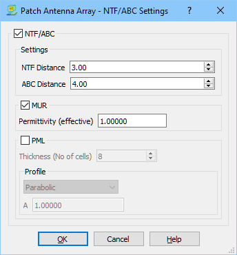
The Settings frame allows for defining the distance between NTF Box and absorbing boundary conditions (ABC) and antenna object.
Absorbing boundary box of MUR type requires setting effective permittivity value, which is related with material parameters of medium, in which the wave propagates. It is used by the software to calculate the correct phase velocity of the wave to assure effective wave absorption. Incorrect assumption of the effective permittivity increases the level of spurious reflections from the ABC. By default it is assumed that the medium is air and the effective permittivity value is set to 1.
Absorbing boundary box of PML type requires specification of the matching layer thickness (expressed in the number of FDTD cells) and selection of the conductivity profile from the following:
· Parabolic (used in most usual applications) - conductivity varies as: A*x^2, where x=(distance from PML edge)/(PML thickness) and A set in the dialogue,
· Exponential - conductivity varies as: A*exp(B*x) with x defined as above, and A, B set in the dialogue.