9.1 Patch Antenna Array Structure
The ![]() button in Antenna Array tab and Model->Patch Antenna Array >Patch Antenna Array... command from main menu invoke Patch Antenna Array dialogue for defining required configuration of patch antenna array.
button in Antenna Array tab and Model->Patch Antenna Array >Patch Antenna Array... command from main menu invoke Patch Antenna Array dialogue for defining required configuration of patch antenna array.

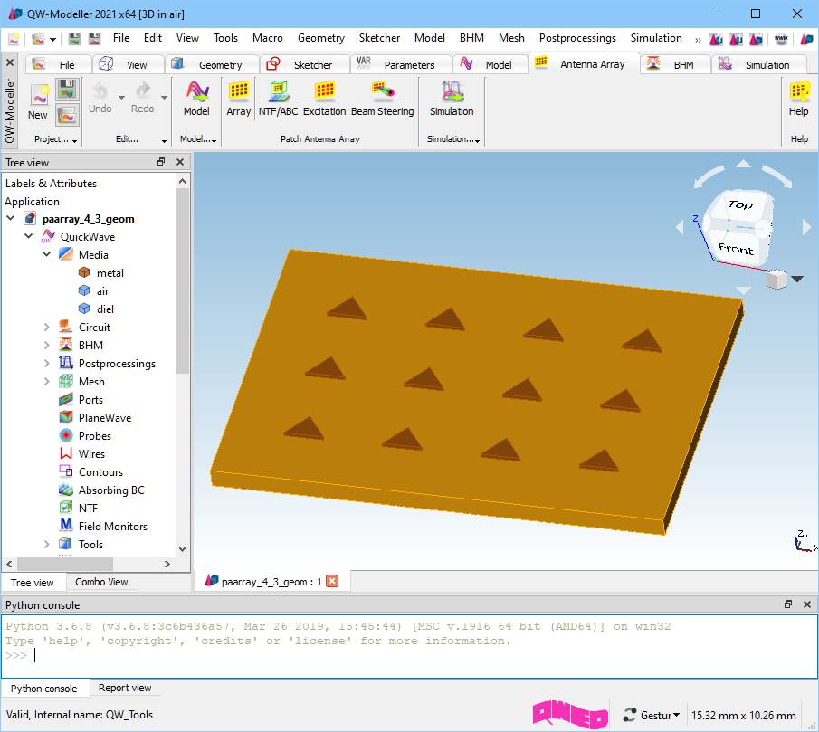
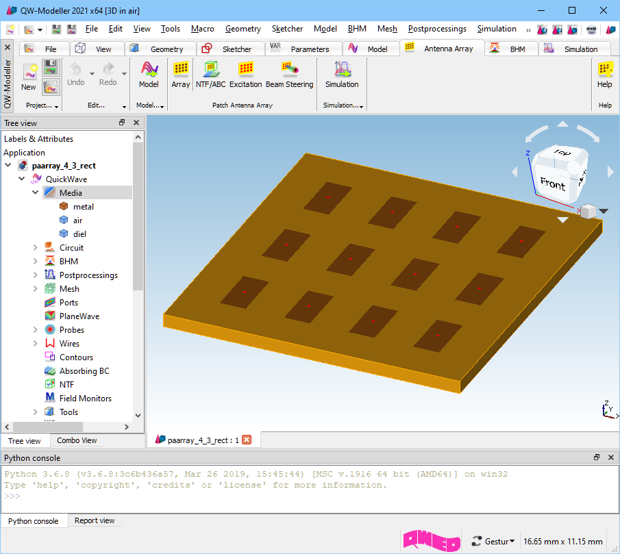
Patch antenna array with Nx=4 and Ny=3.
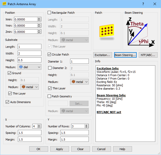
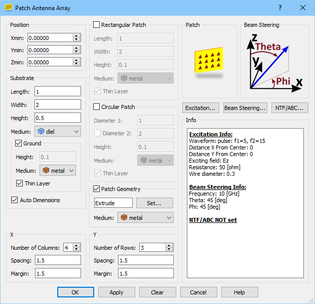
In the Position frame the coordinates of the starting position of the patch antenna array (lower left corner of the substrate) in all three directions should be set.
The Substrate frame allows for defining dimensions of the substrate and selecting its material. If the Auto Dimensions option is checked, the width and length of the substrate will be calculated automatically according to the size of the patches, their number, spacing between them, and margin from substrate’s edges. By setting Ground option – the ground plane with the same lateral dimensions will be added at the bottom of the substrate. The ground plane can be defined as an infinitely thin metal layer (metal layers of zero thickness) – see Thin Layer chapter for more information.
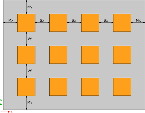
The X frame allows for setting Nx (Number of Columns), Sx (Spacing) and Mx (Margin) parameters in X-direction.
The Y frame allows for setting Ny (Number of Rows), Sy (Spacing) and My (Margin) parameters in Y-direction.
The Excitation… button opens the Patch Antenna Array – Excitation dialogue for including and changing excitation points settings for patch antenna array.
The Beam Steering… button opens the Patch Antenna Array – Beam Steering dialogue for including and setting the required direction of main radiation beam.
The NTF/ABC… button opens the Patch Antenna Array – NTF/ABC Settings dialogue for setting absorbing boundary conditions and NTF Box necessary for calculating the radiation pattern.
The Info frame displays information about excitation, beam steering, and absorbing boundary conditions settings.
There are three types of individual patch shape available:
· Rectangular
· Circular
· Geometry
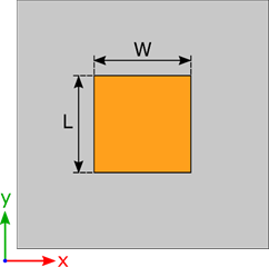
Rectangular type:
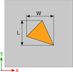
The Rectangular type of individual patch shape allows for defining the rectangle as a patch shape. The rectangular patch is defined with its Length (L), Width (W), Height, and Medium. The rectangular patch can be defined as an infinitely thin metal layer (metal layers of zero thickness) – see Thin Layer chapter for more information.
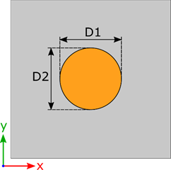
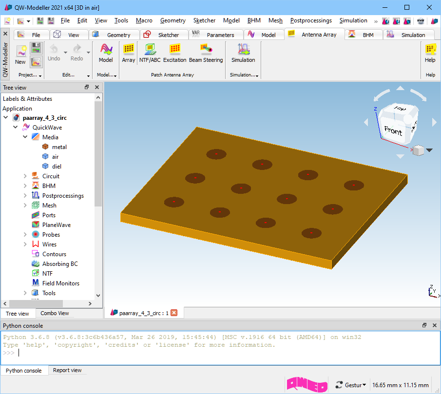
Circular type:
The Circular type of individual patch shape allows for defining the circle as a patch shape. The circular patch is defined with its Diameter1 (D1), Height, and Medium. The Diameter2 (D2) is not available for editing in this release of QW-Modeller and D2=D1. The circular patch can be defined as a infinitely thin metal layer (metal layers of zero thickness) – see Thin Layer chapter for more information.
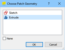
Geometry type:
The Geometry type of individual patch shape allows for defining any form of a patch shape with chosen Medium.
The base shape for this kind of patch type should be defined in the project before creating patch antenna array.
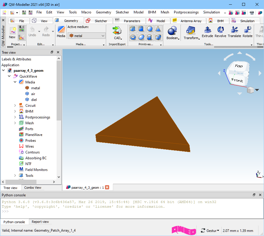
The Set… button opens Choose Patch Geometry for selecting the base object that will be used as a patch shape.