9.4 Patch Antenna Array Beam Steering
The ![]() button in Antenna Array tab and Model->Patch Antenna Array >Patch Antenna Array Beam Steering... command from main menu or Beam Steering… button from Patch Antenna Array dialogue invoke Patch Antenna Array – Beam Steering dialogue for including and setting the required direction of main radiation beam for the patch antenna array.
button in Antenna Array tab and Model->Patch Antenna Array >Patch Antenna Array Beam Steering... command from main menu or Beam Steering… button from Patch Antenna Array dialogue invoke Patch Antenna Array – Beam Steering dialogue for including and setting the required direction of main radiation beam for the patch antenna array.
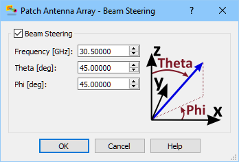
The direction of main radiation beam can be steered by defining φ and θ angles, for which QW-Modeller automatically calculates two-dimensional progression of the excitation signal delay (corresponding to phase shift) within all patches.
A two-dimensional phase progression among the array elements is given by the following equations:
phase_shiftx=k*dx*sin(θ)*cos(φ)
phase_shifty=k*dy*sin(θ)*sin(φ)
where:
k is phase constant defined as 2*π/λ
dx=Sx+W and dy=Sy+L (for rectangular and geometry patch)
dx=Sx+D1 and dy=Sy+D2 (for circular patch)
After relating the phase shifts with delay values (Delayx and Delayy) an effective delay of the excitation signal for particular patch in the array of Nx × Ny size is calculated according to the following equation:
Delayij=i*Delayx + j*Delayy
where:
i=0……Nx
j=0……Ny