1.9 QW-3D Projects
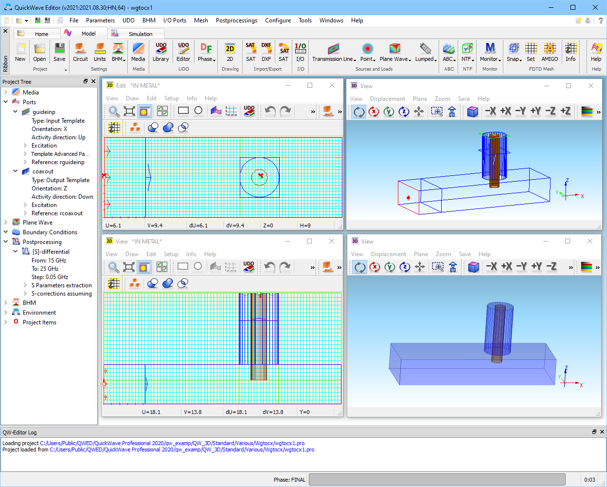
As an example of QW-3D project a coaxial line to waveguide transition considered in ...\Various\Wgtocx\wgtocx1.pro will be presented (thoroughly described in User Guide 3D: S-parameters extraction problems). The project is visualised in four windows. The two on the left are 2D, the two on the right are 3D. Let us note that in the QW-Editor we use in parallel two systems of coordinates. One is the general 3D system of the axes X, Y and Z. The other is a local 2D system bound to a particular 2D Window. The variables of this system are U and V. The local system can be changed using Define Plane dialogue. For example, it can be rotated by a particular angle and in such a case the lines drawn parallel to it will be inclined by this angle with respect to the XY axes of the general 3D system.
The general coordinate system is marked in the3D Window by three short thick axes (coloured red, green and blue, RGB corresponding to XYZ).
The position of the cursor in each of the 2D Windows expressed in the local coordinates is displayed in the lower part of this window. Here we have the U and V components as well as the increments of these components from a chosen (last click) reference point. These incremental components are set to zero after we press the left mouse button. To be able to compare the local components with the general components it is sufficient to press the space bar and we can see the Coordinates dialogue with the position of the point in the XYZ coordinate system. Pressing the space bar once again closes the Coordinates dialogue with XYZ coordinates.
Note that the content and position of the toolbars can be individually set in each window in a standard Windows system manner.
See also User Guide 3D for QW-3D examples description.