Home > QuickWave Editor > 2 2D Window
2 2D Window
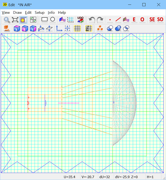
The ![]() button in Home tab and Windows->Open->2D Window (Edit/View)... command from main menu invoke 2D Window, also called 2D Edit or 2D View window.
button in Home tab and Windows->Open->2D Window (Edit/View)... command from main menu invoke 2D Window, also called 2D Edit or 2D View window.
The 2D Window user interface contains main interface elements in a form of Toolbars and Menu.

Each of the 2D Window describes a chosen section of the 3D structure. 2D Window is of Edit and View type. The structure can be defined / modified only in a 2D Window displaying the XY plane. The XY plane is a natural base for investigating, introducing and correcting the elements of which the project is composed. 2D Window in the XZ or YZ planes is for visualisation only. It should be noted that when a 2D Window describes the considered structure in XZ or YZ plane some of the commands of the Draw and Edit groups are blocked. Thus in practical operation of the software when we have problems with using one of those commands, most probably it is the result of the cursor being focused in a window other than 2D one defined in XY plane.
It is worth noting that:
· the user can open as many 2D Windows as he finds appropriate to display the structure.
· 2D Window can display a section of the considered structure in XY, XZ or YZ planes. The plane can be chosen using Define Plane dialogue.
· 2D Window allows verifying the dimensions of the structure. The actual cursor position in a general coordinate system can be displayed in a Coordinates dialogue opened by pressing the keyboard’s space bar. To get the precise position of a particular point of the structure it is advisable to use Zoom function and possibly modify snapping of the cursor position readings in the Grid/Snap Parameters dialogue. All the distances are displayed in current units set in the Units dialogue. Default units are millimetres.
· 2D Window displays the actual FDTD meshing, which can be modified using Mesh Parameters dialogue. Mesh/Splanes Info dialogue provides additional information about the meshing including the number of FDTD cells used in the project.
· in the title bar of 2D Window we can see what the default medium used in the project is. “IN METAL” indicating that all the space not occupied by the elements of the project will be filled with the medium “metal”. “IN AIR” indicating that all the space not occupied by the elements of the project will be filled with the medium “air”. The default medium can be changed in Circuit dialogue, where we have two alternatives: metal (also referred to as PEC - Perfect Electric Conductor) or air.
Depending on the circuit type, there are different ways for displaying the project:
Home > QuickWave Editor > 2 2D Window