6.1.4 PML Wall
The ![]() button in the 2D Window toolbar and Draw->I/O Ports... command from 2D Window menu invoke I/O Ports dialogue which can be used for drawing ports in a manual way.
button in the 2D Window toolbar and Draw->I/O Ports... command from 2D Window menu invoke I/O Ports dialogue which can be used for drawing ports in a manual way.
We suggest alternative and more convenient way of introducing this type of absorbing boundary condition using ABC Wall or ABC Box dialogue.
PML Wall describes a port used for absorbing termination of a chosen rectangular part of the FDTD mesh.
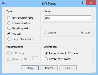
It is not used for extracting any parameters for further postprocessing. The absorbing boundary condition is Perfectly Matched Layer.
Before clicking Draw, the user must specify whether the port is Perpendicular to XY plane or Parallel to XY plane, which entails that it will be drawn as a line (with the port height set in Define Level dialogue) or rectangle, respectively using mouse pointer or Keyboard Entry dialogue.
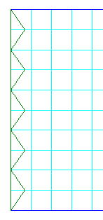
The port in XZ and YZ planes is introduced in a way similar to elements with the only difference that their base is a straight line while the elements have polygonal bases.
The port in XY planes is introduced in a similar way as a rectangular base of an element.
For more details regarding Perfectly Matched Layer absorbing boundary conditions refer to Perfectly Matched Layer.