6.5 Point Source and Probe Port
The ![]() command from Add section in
command from Add section in ![]() button in Model tab and I/O Ports->Point->(Add) Source... command from main menu invoke Point/Probe dialogue for adding point port with default settings for source.
button in Model tab and I/O Ports->Point->(Add) Source... command from main menu invoke Point/Probe dialogue for adding point port with default settings for source.
The ![]() command from Add section in
command from Add section in ![]() button in Model tab and I/O Ports->Point->(Add) Probe... command from main menu invoke Point/Probe dialogue for adding point port with default settings for probe.
button in Model tab and I/O Ports->Point->(Add) Probe... command from main menu invoke Point/Probe dialogue for adding point port with default settings for probe.
This dialogue can be also opened for adding or editing the point port from Point Sources and Probes dialogue.
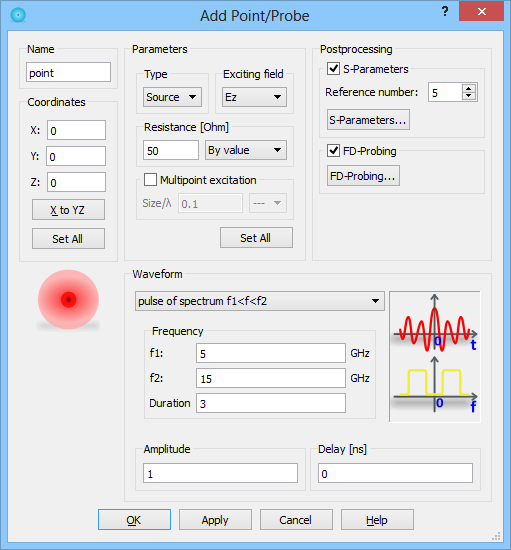
In the Name field the point port name, used for identifying the point, should be put. There are two types of Point Port, source and probe. After setting the Type to Probe, the Waveform part becomes not active.
In the Coordinates frame, values of the Point position in all three directions should be set.
Other parameters such as exciting field component to which the port is connected or its resistance are set. The By value combo box allows setting infinite resistance (+INF) or setting automatic adjustment (Auto adjust).
Options available in Postprocessing frame, enable declaring if particular Point should take a part in S-Parameters and FD-Probing calculations. To disable either of those options it is necessary to uncheck S-Parameter and FD-Probing checkboxes, respectively. S-Parameters… and FD-Probing… buttons allow passing to the S-Parameters and FD-Probing post-processings dialogues, respectively, and configuring those post-processings.
The Waveform frame enables setting the excitation parameters like, Waveform, Frequency Range, Amplitude, and Delay. See Waveform chapter for more information.
It is advised to refer to Point source and Point probe for more details regarding point sources and probes.