5.1.2 Point source
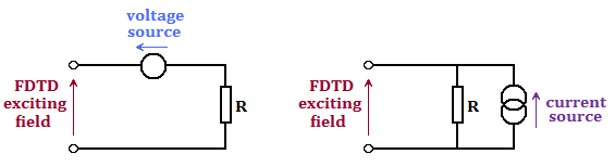
In QuickWave the Point sources (lumped sources) with user controlled available power or injected current are available. Point source describes a point port defined by its current and voltage at certain nodes. We can consider lumped ports only across one FDTD cell. An equivalent circuit model of the lumped port consists of a voltage source in series with a resistor, or equivalently, a current source in parallel with a resistor. The two models are equivalent when (current source)=(voltage source) / R. It reduces to a resistor if the source is deactivated.
An equivalent circuit model of the lumped source.
In the case of Point source port the user must define:
a field component to which the port is connected,
internal resistance of the port (a value from the 0..+INF range, or self adjusted for good energy coupling between the source and the neighbouring FDTD mesh, in which case an appropriate value of resistance is calculated by the software).
The Point source become electric voltage/current sources if the port is connected to one of the electric field components, and magnetic voltage/current sources if the port is connected to one of the magnetic field components.
The verification of the position and parameters (resistance and field component) of the Point source can be made during the electromagnetic simulation using Effective FDTD mesh grid.
For Point source port, the user will additionally define the source Waveform, Amplitude and Delay. Setting no excitation waveform effectively transforms the source into a probe. The Point source port can be used in the following cases:
· as a virtual source in eigenvalue problems (resonant modes, their frequencies and Q-factors in a resonator, see User Guide 3D: Dielectric resonator example,
· as a dipole (in the analysis of dipole-excited antenna problems, see User Guide 3D: Two dipoles in free space excited in phase example),
· as a lumped source of finite output impedance (in the calculations of embedding impedance for lumped elements, see User Guide 3D: Wire antenna example).
In the last case, the point source should be placed in a one-cell gap between two metal elements. If the gap (for example between two metal plates) is larger than one cell, the point source should be connected to the metal elements with additional wire elements. It is also possible to place a point source directly on the wire. This feature will be particularly convenient in the analysis of wire antennas: changes in the meshing will not need to be associated with changing the size of the gap, to keep it equal to one FDTD cell. The Point source port placed on the wire will “cut” a gap in the wire and work directly in that gap.
The Point source port can take part in the following post-processing algorithms:
FD-Probing, which stands for frequency domain probing, and means that Fourier transforms of terminal voltage across the resistor and current through the resistor will be calculated,
S-Parameters post-processing as port No., which includes the Point source port in the S-parameters extraction system together with Transmission line ports (template port, modal port).
It is worth noting at this point that if a Point source is included in the S-Parameters post-processing, its resistance R serves as a reference resistance for separating the incident and reflected waves. However, if R=+INF or R=0, then 50 Ω is taken as a reference.
Note that FD-Probing post-processing also produces reflection loss as one of its results. It is denoted by a symbol S_number, where “number” is the value of R (or 50, if R=+INF or R=0, in which case 50 Ω is taken as a reference).
The interpretation of lumped sources is somewhat different in QW-V2D than in QW-3D. In view of the axial symmetry, any point becomes a ring and thus a point source becomes a ring source with the angular distribution of current as declared in Circuit dialogue.
The point source may be divided into two main groups described below in the following sub-sections.
5.1.2.1 Lumped resistive source
The Point source of finite resistance (0<R<+INF) is the lumped resistive source. For such source the value of Amplitude is a square root of time-maximum power available from the source:
Amplitude = 0.5*(voltage source)/sqrt(R) = 0.5*(current source)*sqrt(R),
where voltage source and current source are amplitudes of the two equivalent sources as shown in Equivalent circuit model of the lumped source picture.
It is advised to refer to I/O Port Parameters for point sources/probes or lumped impedances for a detailed discussion.
5.1.2.2 Ideal voltage and current source
An ideal voltage and current source are obtained by assigning an appropriate resistance value to a lumped source. We get:
an ideal voltage source if resistance is set to zero,
an ideal current source if resistance is set to +INF.
For R=0 or R=+INF, Amplitude corresponds to the amplitude of voltage source or current source, respectively, scaled with free space impedance:
(voltage source)= Amplitude *sqrt(376.73..),
(current source)= Amplitude /sqrt(376.73..).
In such cases, the value of power available calculated by the Power Available post-processing is equal to power that would be dissipated if the source were loaded with free space impedance (376.73.. Ω).