2.3.7 Disconnecting NTF walls
The principle of near-to-far field transformation requires that the radiating structure be surrounded by a closed surface, unless symmetries are explored. This is the approach taken in the antenna examples so far: for a majority, NTF surface has been a closed cuboidal box while in horn2.pro a ground plane has been modelled as a symmetry plane.
There are, however, cases when we may wish to calculate radiation patterns using only some of the pickup walls. A practical application would be to directly compare simulated and measured results, with near-field measurements taken over a single aperture. Another case is more FDTD-specific: due to numerical dispersion and the necessity to average either electric or magnetic field components across each pickup wall, a wave that physically propagates in one direction may numerically generate a non-physical backward lobe. A simple way to see whether a particular backlobe is physical or a numerical artefact is to disconnect the pickup surface “looking” in its direction from NTF transform and to check how the results change.
To exemplify this approach, consider the patch1.pro example again. The |Etheta| curve at 5.525 GHz, previously shown in Fig. 2.3.3-3, is repeated in Fig. 2.3.7-1(blue curve). It has main beams around ±30°but also two weaker beams around ±160°. The user may wonder whether these are the actual downward propagating waves or numerical images of the upward ones. QW-Simulator allows excluding selected NTF walls from calculations. In the Radiation Patterns dialogue, ![]() button opens the Pickup Walls dialogue shown in the right part of Fig. 2.3.7-1. By default, all six walls are checked and take part in NTF transformation. The user may uncheck and exclude any combination of them from one NTF post-processing calculation.
button opens the Pickup Walls dialogue shown in the right part of Fig. 2.3.7-1. By default, all six walls are checked and take part in NTF transformation. The user may uncheck and exclude any combination of them from one NTF post-processing calculation.

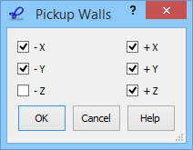
Fig. 2.3.7-1 Radiation pattern of patch1.pro at 5.525 GHz obtained with a complete NTF box (blue) and after disconnecting bottom pickup wall (green) using the dialogue on the right.
To check whether EM energy is really radiated downwards by the considered patch, we exclude the bottom (–Z) wall from NTF transformation. The green curve of Fig. 2.3.7-1is obtained. The ±160°lobes are reduced, compared to the complete NTF transform, and the green curve is practically monotone for large angles. This indicates that the patch does radiate through the –Z pickup wall. By comparing radiation efficiency and radiated power in the two cases we conclude that 2.34% of the total power radiated by the antenna exits the NTF box through the –Z wall.