2.6.6 Circular polarisation in radiation pattern
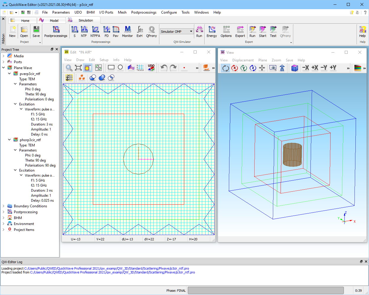
In QW-3D the user can watch the radiation pattern in either linear or circular polarisation mode. The linear mode has been discussed in earlier sctions (see Plane wave without the scatterer), so we will focus below on the explanation of the latter one introduced in the example ..\Scattering\Plwave\p3cir_ntf.pro shown in the Fig. 2.6.6-1. In principle, the example is based on the previously introduced p3cir.pro (see More plane wave examples), where two plane waves with perpendicular polarisations are excited, thus, producing right-hand circular polarisation propagating along the X-axis. In p3cir_ntf.pro, metal cylinder of radius 5 mm, height 10 mm is placed in a total field region to produce the scattered field.
Fig. 2.6.6-1 QW-Editor display of p3cir_ntf.pro example.
Fig. 2.6.6-2shows the radiation pattern in the circular polarisation mode calculated in the XY-plane. As one might expect, forward scattered field is only right-hand polarised (Phi = 0 deg), whereas backward scattering is left-hand polarised (Phi = ±180 deg).
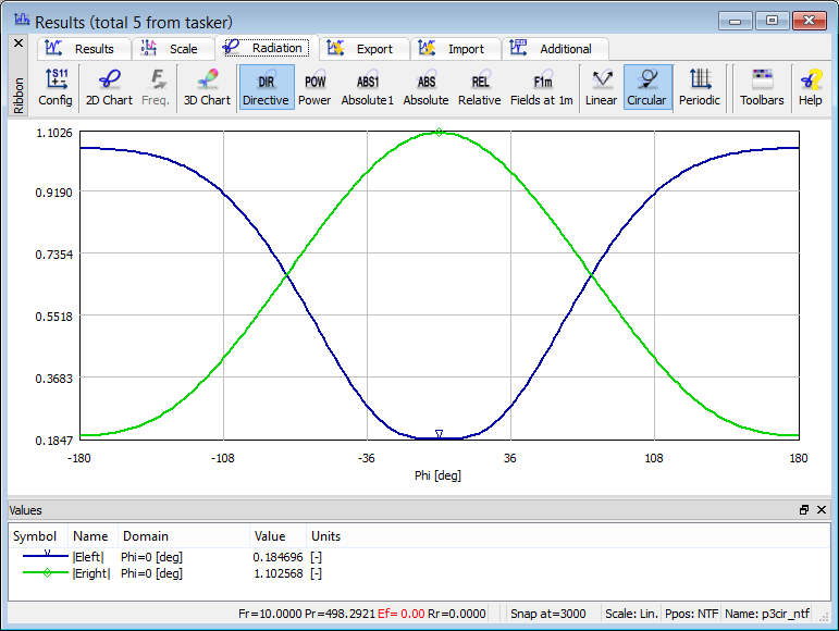
Fig. 2.6.6-2 Scattering pattern obtained for p3cir_ntf.pro example.
Circular polarisation mode can also be applied to the inspection of linear polarisation. If the beam is perfectly linearly polarised, we will obtain left- and right-hand polarisations of the same level. Fig. 2.6.6-3and Fig. 2.6.6-4show radiation patterns in the linear and circular polarisation modes, respectively, calculated for the plw2m1.pro (see Plane wave with the scatterer). It can be noticed that linear polarisation (Etheta) is decomposed on left- and right hand polarisations of the exactly same level.
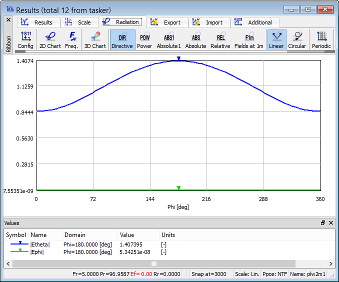
Fig. 2.6.6-3 Scattering pattern in the linear polarisation mode for plw2m1.pro example.
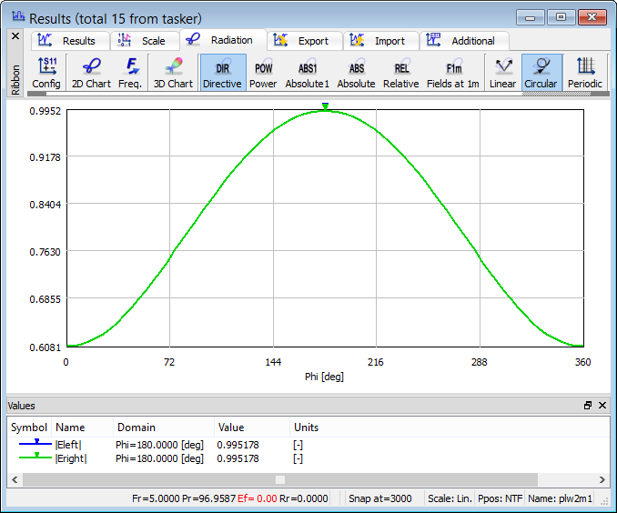
Fig. 2.6.6-4 Scattering pattern in the circular polarisation mode for plw2m1.pro example.