2.6.2 Plane wave with the scatterer
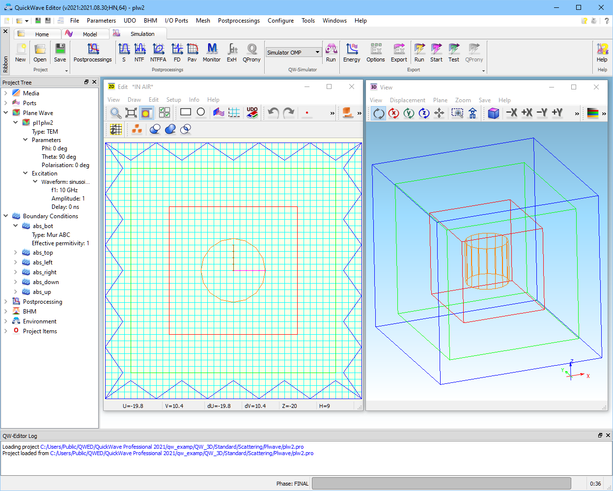
Let us now watch the scattering from a metal cylinder of radius 5 mm, height 10 mm, placed 15 mm above the bottom absorbing wall. The project is stored as ..\Scattering\Plwave\plw2.pro. The view of the project is presented in Fig. 2.6.2-1.
Fig. 2.6.2-1 Plane wave box with a scatterer inside (plw2.pro).
Then click ![]() button in Simulationtab of QW-Editor to export the files, call the QW‑Simulator, and start the simulation. After a few hundred of iterations press
button in Simulationtab of QW-Editor to export the files, call the QW‑Simulator, and start the simulation. After a few hundred of iterations press ![]() button in 2D/3D Fields tab of QW-Simulator to open 2D/3D Fields Distribution window. A picture as in Fig. 2.6.2-2appears.
button in 2D/3D Fields tab of QW-Simulator to open 2D/3D Fields Distribution window. A picture as in Fig. 2.6.2-2appears.
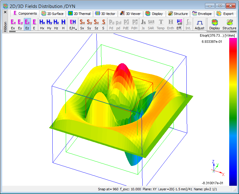
Fig. 2.6.2-2 Field distribution with the scatterer with excitation conditions as in case of Fig. 2.6.1-6.
Stop the simulation by clicking ![]() button in Runtab of QW-Simulator and return to QW-Editor. Open Edit Plane Wave dialogue and introduce Phi=45 and click OK. Press
button in Runtab of QW-Simulator and return to QW-Editor. Open Edit Plane Wave dialogue and introduce Phi=45 and click OK. Press ![]() button to run the simulation. After a few hundred of iterations press
button to run the simulation. After a few hundred of iterations press ![]() button to open 2D/3D Fields Distribution window. A picture as in Fig. 2.6.2-3appears.
button to open 2D/3D Fields Distribution window. A picture as in Fig. 2.6.2-3appears.
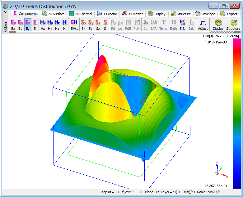
Fig. 2.6.2-3 Field distribution with the scatterer with excitation conditions as in case of Fig. 2.6.1-7.
Stop the simulation clicking ![]() and return to QW-Editor.
and return to QW-Editor.
You can now open plw2m1.pro with below given settings or modify plw2.pro as described below. Open Edit Plane Wave dialogue and set the exciation parameters as in Fig. 2.6.2-4. After pressing OK, invoke Near To Far dialogue (![]() button in Simulationtab of QW-Editor). Please check Near To Far, specify three NTF frequencies: 5 10 15 (using space as a separator between them), and click OK.
button in Simulationtab of QW-Editor). Please check Near To Far, specify three NTF frequencies: 5 10 15 (using space as a separator between them), and click OK.
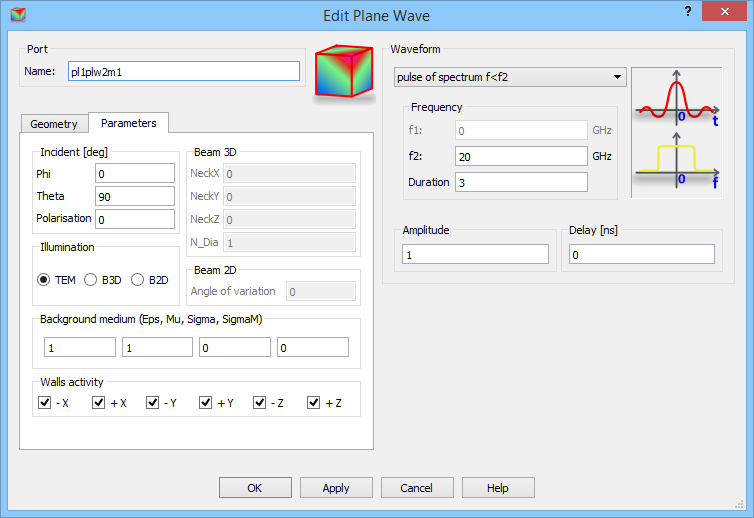
Fig. 2.6.2-4 Edit Plane Wave dialogue settings for scattering pattern calculations.
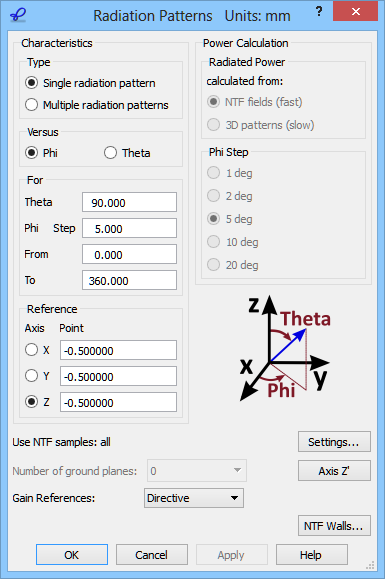
Fig. 2.6.2-5 Radiation Patterns dialogue with parameters for calculation of scattering patterns in plw2m1.pro.

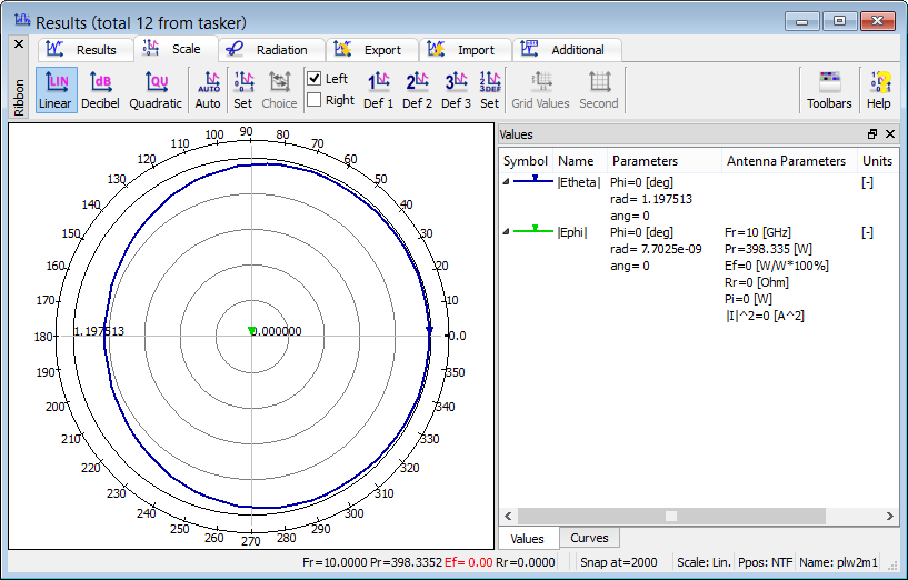
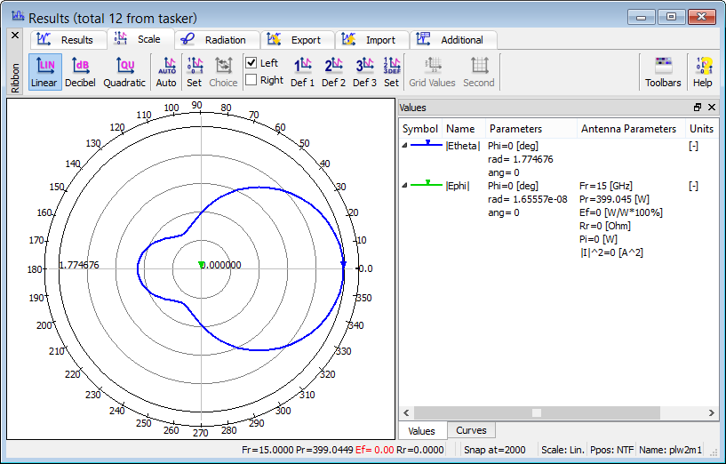
Fig. 2.6.2-6 Scattering patterns in plw2m1.pro calculated for 5, 10 and 15 GHz at Phi=0 incidence.
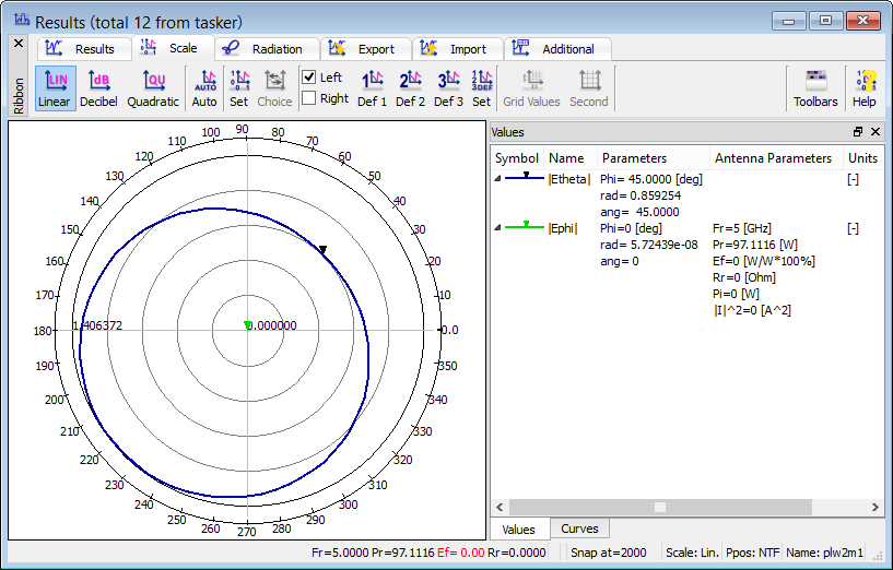
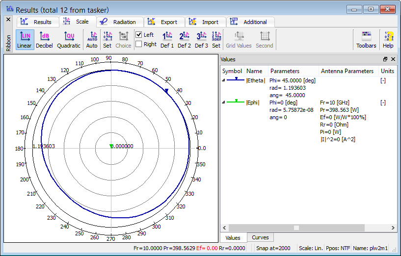
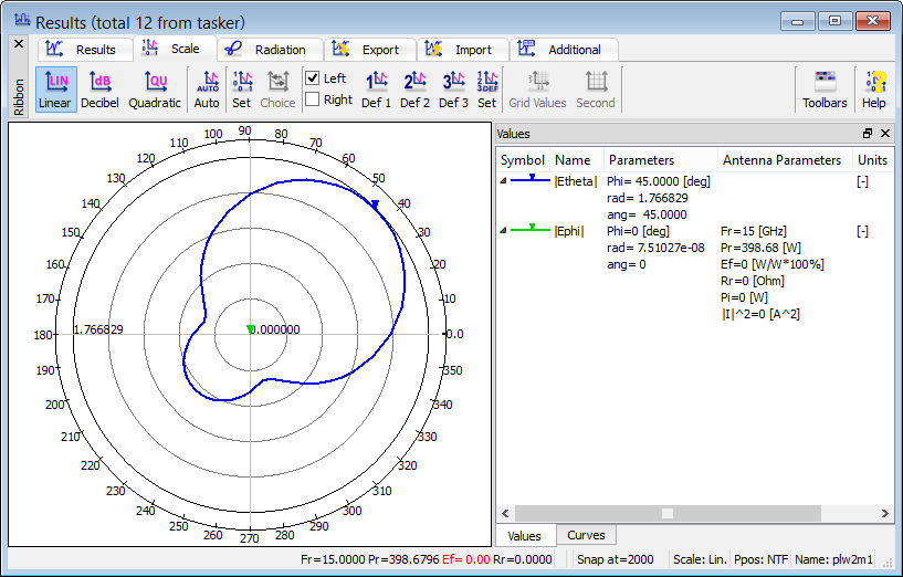
Fig. 2.6.2-7 Scattering patterns in plw2m1.pro calculated for 5,10 and 15 GHz at Phi=45 deg incidence.
Click ![]() button in Simulationtab of QW-Editor. After a few hundred of iterations press open Resultswindow with 2D radiation pattern results by pressing
button in Simulationtab of QW-Editor. After a few hundred of iterations press open Resultswindow with 2D radiation pattern results by pressing ![]() button in Resultstab of QW-Simulator. The Radiation Patterns dialogue appears. In this example, the settings shown in Fig. 2.6.2-5 should be made. Those on the left hand side (Reference Axis Z, chart plotted Versus Phi, for Theta 90) mean that the radiation pattern in the XY-plane will be calculated. The Phi Step will be 5deg. The coordinates of the Reference Point for phase calculations will be (-0.5 mm, -0.5 mm, -0.5 mm).
button in Resultstab of QW-Simulator. The Radiation Patterns dialogue appears. In this example, the settings shown in Fig. 2.6.2-5 should be made. Those on the left hand side (Reference Axis Z, chart plotted Versus Phi, for Theta 90) mean that the radiation pattern in the XY-plane will be calculated. The Phi Step will be 5deg. The coordinates of the Reference Point for phase calculations will be (-0.5 mm, -0.5 mm, -0.5 mm).
Now press OK to see the radiation patterns (or in our case rather the scattering patterns). The first one shown is for the first NTF frequency declared in QW-Editor, i.e. 5 GHz. After pressing f we obtain the characteristic for 10 GHz and pressing f once again we obtain the characteristic for 15 GHz. All are shown in Fig. 2.6.2-6.
Stop the simulation clicking ![]() button and return to QW-Editor. Open Edit Plane Wave dialogue and introduce Phi=45. Click
button and return to QW-Editor. Open Edit Plane Wave dialogue and introduce Phi=45. Click ![]() button to run the simulation. After a few hundred of iterations press
button to run the simulation. After a few hundred of iterations press ![]() button. After pressing OK in Radiation Patterns dialogue (Fig. 2.6.2-5) we obtain the characteristics presented in Fig. 2.6.2-7for 5 GHz, 10 GHz and 15 GHz, respectively, for Plane wave incident in Phi=45 deg and Theta=90 deg.
button. After pressing OK in Radiation Patterns dialogue (Fig. 2.6.2-5) we obtain the characteristics presented in Fig. 2.6.2-7for 5 GHz, 10 GHz and 15 GHz, respectively, for Plane wave incident in Phi=45 deg and Theta=90 deg.