
1.1.4 Sketcher
QW-Modeller Sketcher tab options are arranged in sections, which allow the user creating the project geometry and assigning material properties to each object.
Project section
Project section contains the following commands:
![]() - creates new QW-Modeller project. See New Project chapter for more information.
- creates new QW-Modeller project. See New Project chapter for more information.
![]() - saves QW-Modeller project with the current name (if the project has not been saved yet, the Save QW-Modeller Project dialogue will appear).
- saves QW-Modeller project with the current name (if the project has not been saved yet, the Save QW-Modeller Project dialogue will appear).
![]() - opens QW-Modeller (or other supported format) project.
- opens QW-Modeller (or other supported format) project.
![]() - opens Save QW-Modeller Project dialogue for introducing project file name.
- opens Save QW-Modeller Project dialogue for introducing project file name.
![]() - constructs QuickWave components tree in the Tree View.
- constructs QuickWave components tree in the Tree View.
See Supported formats chapter for more information.
Edit section


Edit section contains the following commands:
![]() - undo operation
- undo operation
![]() - redo operation
- redo operation
![]() - copy selected object(s)
- copy selected object(s)
![]() - paste copied object(s)
- paste copied object(s)
![]() - duplicate selected object(s)
- duplicate selected object(s)
![]() - select all objects
- select all objects
![]() - box selection in the 3D view
- box selection in the 3D view
Sketch section

Sketch subsection

Sketch subsection contains the following commands:
![]() - creates a new sketch and switch to the sketch editing mode
- creates a new sketch and switch to the sketch editing mode
![]() - edits the selected sketch
- edits the selected sketch
![]() - closes the edition of selected sketch
- closes the edition of selected sketch
![]() - creates a rectangle in the sketch
- creates a rectangle in the sketch
![]() - creates a circle in the sketch
- creates a circle in the sketch
![]() - creates an ellipse in the sketch
- creates an ellipse in the sketch
![]() - creates an arc of ellipse in the sketch
- creates an arc of ellipse in the sketch
![]() - creates a line in the sketch
- creates a line in the sketch
![]() - creates a polyline in the sketch
- creates a polyline in the sketch
![]() - creates a point in the sketch
- creates a point in the sketch
![]() - creates an arc in the sketch
- creates an arc in the sketch
![]() - creates a clone of the geometry with respect to the last selected point
- creates a clone of the geometry with respect to the last selected point
![]() - creates a simple copy of the geometry with respect to the last selected point
- creates a simple copy of the geometry with respect to the last selected point
![]() - creates symmetric geometry with respect to the last selected line or point
- creates symmetric geometry with respect to the last selected line or point
![]() - creates a rectangular array pattern of the geometry with respect to the last selected point
- creates a rectangular array pattern of the geometry with respect to the last selected point
![]() - creates a fillet between two lines or at a coincident point in the sketch
- creates a fillet between two lines or at a coincident point in the sketch
![]() - creates triangle in the sketch
- creates triangle in the sketch
![]() - creates square in the sketch
- creates square in the sketch
![]() - creates pentagon in the sketch
- creates pentagon in the sketch
![]() - creates hexagon in the sketch
- creates hexagon in the sketch
![]() - creates heptagon in the sketch
- creates heptagon in the sketch
![]() - creates octagon in the sketch
- creates octagon in the sketch
![]() - maps sketch to the selected face
- maps sketch to the selected face
![]() - reorients the selected sketch
- reorients the selected sketch
![]() - views sketch perpendicular to the sketch plane
- views sketch perpendicular to the sketch plane
![]() - opens Sketcher Validation dialogue in the Task Panel for sketch validation
- opens Sketcher Validation dialogue in the Task Panel for sketch validation
![]() - merges the selected sketches
- merges the selected sketches
Sketch Tools Subsection

Sketch Tools subsection contains the following commands:
![]() - creates a coincident constraint on the selected item
- creates a coincident constraint on the selected item
![]() - fixes a point onto an object
- fixes a point onto an object
![]() - creates a vertical constraint on the selected item
- creates a vertical constraint on the selected item
![]() - creates a horizontal constraint on the selected item
- creates a horizontal constraint on the selected item
![]() - creates a parallel constraint between two lines
- creates a parallel constraint between two lines
![]() - creates a perpendicular constraint between two lines
- creates a perpendicular constraint between two lines
![]() - creates a tangent constraint between two entities
- creates a tangent constraint between two entities
![]() - creates an equality constraint between two lines or between circles and arcs
- creates an equality constraint between two lines or between circles and arcs
![]() - creates a symmetry constraint between two points with respect to a line or a third point
- creates a symmetry constraint between two points with respect to a line or a third point
![]() - creates a lock constraint on the selected item
- creates a lock constraint on the selected item
![]() - fixes the horizontal distance between two points or line ends
- fixes the horizontal distance between two points or line ends
![]() - fixes the vertical distance between two points or line ends
- fixes the vertical distance between two points or line ends
![]() - fixes a length of a line or the distance between a line and a vertex
- fixes a length of a line or the distance between a line and a vertex
![]() - fixes the radius of a circle or an arc
- fixes the radius of a circle or an arc
![]() - fixes the angle of a line or the angle between two lines
- fixes the angle of a line or the angle between two lines
![]() - produces closed shape by linking the end point of element with next elements' starting point
- produces closed shape by linking the end point of element with next elements' starting point
![]() - links the end point of element with next elements' starting point
- links the end point of element with next elements' starting point
![]() - selects the constraints associated to the selected elements
- selects the constraints associated to the selected elements
![]() - selects the origin point
- selects the origin point
![]() - selects the vertical axis
- selects the vertical axis
![]() - selects the horizontal axis
- selects the horizontal axis
![]() - selects constraints that are redundant
- selects constraints that are redundant
![]() - selects constraints that are conflicting
- selects constraints that are conflicting
![]() - selects elements that are associated with constraints
- selects elements that are associated with constraints
![]() - shows all internal geometry / hides unused internal geometry
- shows all internal geometry / hides unused internal geometry
![]() - trims an edge with respect to the picked position
- trims an edge with respect to the picked position
![]() - creates an edge linked to an external geometry
- creates an edge linked to an external geometry
Geometry section

Geometry section contains the following commands:
![]() - switches to Geometry tab of QW-Modeller Ribbon
- switches to Geometry tab of QW-Modeller Ribbon
Model section
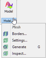
Model section contains the following commands:
![]() - switches to Model tab of QW-Modeller Ribbon
- switches to Model tab of QW-Modeller Ribbon
![]() - opens Boundary Conditions dialogue with options for project boundaries configuration. See Borders chapter for more information.
- opens Boundary Conditions dialogue with options for project boundaries configuration. See Borders chapter for more information.
![]() - opens Mesh Settings dialogue with options for FDTD mesh configuration. See Mesh Settings chapter for more information.
- opens Mesh Settings dialogue with options for FDTD mesh configuration. See Mesh Settings chapter for more information.
![]() - recalculates FDTD mesh.
- recalculates FDTD mesh.
![]() - opens Mesh Inspect dialogue with FDTD mesh information. See Mesh Inspect chapter for more information.
- opens Mesh Inspect dialogue with FDTD mesh information. See Mesh Inspect chapter for more information.
Help section
![]()
Help section contains the following command:
![]() - opens help for Sketcher commands (present chapter)
- opens help for Sketcher commands (present chapter)