
1.1.3 Geometry
QW-Modeller Geometry tab options are arranged in sections, which allow the user creating the project geometry and assigning material properties to each object.
Project section
Project section contains the following commands:
![]() - creates new QW-Modeller project. See New Project chapter for more information.
- creates new QW-Modeller project. See New Project chapter for more information.
![]() - saves QW-Modeller project with the current name (if the project has not been saved yet, the Save QW-Modeller Project dialogue will appear).
- saves QW-Modeller project with the current name (if the project has not been saved yet, the Save QW-Modeller Project dialogue will appear).
![]() - opens QW-Modeller (or other supported format) project.
- opens QW-Modeller (or other supported format) project.
![]() - opens Save QW-Modeller Project dialogue for introducing project file name.
- opens Save QW-Modeller Project dialogue for introducing project file name.
![]() - constructs QuickWave components tree in the Tree View.
- constructs QuickWave components tree in the Tree View.
See Supported formats chapter for more information.
Edit section


Edit section contains the following commands:
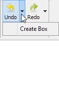
![]() - undo operation
- undo operation
![]() - redo operation
- redo operation
![]() - copy selected object(s)
- copy selected object(s)
![]() - paste copied object(s)
- paste copied object(s)
![]() - duplicate selected object(s)
- duplicate selected object(s)
![]() - select all objects
- select all objects
![]() - box selection in the 3D view
- box selection in the 3D view
Media section

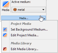
Media section contains the following commands:
![]() - opens Project Media dialogue that allows managing media in the current project. See Project Media for more information.
- opens Project Media dialogue that allows managing media in the current project. See Project Media for more information.
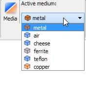
![]() - all media in Project Media with current active medium which will be assigned to the new created geometrical objects
- all media in Project Media with current active medium which will be assigned to the new created geometrical objects
![]() - opens Set Background Medium dialogue that allows choosing one of the two background media (air or metal). See Background Medium for more information.
- opens Set Background Medium dialogue that allows choosing one of the two background media (air or metal). See Background Medium for more information.
![]() - opens Project Media dialogue that allows managing media in the current project. See Project Media for more information.
- opens Project Media dialogue that allows managing media in the current project. See Project Media for more information.
![]() - opens Media Library dialogue that allows managing media database available for all projects. See Media Library for more information.
- opens Media Library dialogue that allows managing media database available for all projects. See Media Library for more information.
Import/Export section
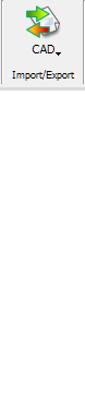
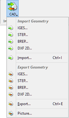
![]() - imports geometry from the IGES file.
- imports geometry from the IGES file.
![]() - imports geometry from the STEP file.
- imports geometry from the STEP file.
![]() - imports geometry from the BREP file.
- imports geometry from the BREP file.
![]() - imports planar geometry from the DXF file.
- imports planar geometry from the DXF file.
![]() - imports geometry from the CAD file to the current project.
- imports geometry from the CAD file to the current project.
![]() - exports selected geometrical object(s) to the IGES file.
- exports selected geometrical object(s) to the IGES file.
![]() - exports selected geometrical object(s) to the STEP file.
- exports selected geometrical object(s) to the STEP file.
![]() - exports selected geometrical object(s) to the BREP file.
- exports selected geometrical object(s) to the BREP file.
![]() - exports selected planar geometrical object(s) to the DXF file.
- exports selected planar geometrical object(s) to the DXF file.
![]() - exports selected geometrical object(s) to the CAD file.
- exports selected geometrical object(s) to the CAD file.
![]() - allows exporting the current 3D view to the graphic file
- allows exporting the current 3D view to the graphic file
See Supported formats chapter for more information.
Primitives section
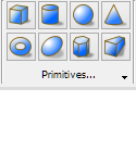
Primitives section contains the following commands:
![]() - opens Create Box dialogue with box parameters. See Box chapter for more information.
- opens Create Box dialogue with box parameters. See Box chapter for more information.
![]() - opens Create Cylinder dialogue with cylinder parameters. See Cylinder chapter for more information.
- opens Create Cylinder dialogue with cylinder parameters. See Cylinder chapter for more information.
![]() - opens Create Sphere dialogue with sphere parameters. See Sphere chapter for more information.
- opens Create Sphere dialogue with sphere parameters. See Sphere chapter for more information.
![]() - opens Create Cone dialogue with cone parameters. See Cone chapter for more information.
- opens Create Cone dialogue with cone parameters. See Cone chapter for more information.
![]() - opens Create Torus dialogue with torus parameters. See Torus chapter for more information.
- opens Create Torus dialogue with torus parameters. See Torus chapter for more information.
![]() - opens Create Ellipsoid dialogue with ellipsoid parameters. See Ellipsoid chapter for more information.
- opens Create Ellipsoid dialogue with ellipsoid parameters. See Ellipsoid chapter for more information.
![]() - opens Create Prism dialogue with prism parameters. See Prism chapter for more information.
- opens Create Prism dialogue with prism parameters. See Prism chapter for more information.
![]() - opens Create Wedge dialogue with wedge parameters. See Wedge chapter for more information.
- opens Create Wedge dialogue with wedge parameters. See Wedge chapter for more information.
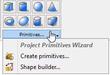
![]() - opens Geometric Primitives dialogue in the Task Panel for primitives creation. See Various Primitives chapter for more information.
- opens Geometric Primitives dialogue in the Task Panel for primitives creation. See Various Primitives chapter for more information.
![]() - opens Create Shape dialogue in the Task Panel with advanced utility for shapes creation. See Shape Builder chapter for more information.
- opens Create Shape dialogue in the Task Panel with advanced utility for shapes creation. See Shape Builder chapter for more information.
Tools section

Tools section contains the following commands:
![]() - contains the following Boolean operations:
- contains the following Boolean operations:
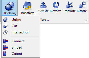
![]() - makes an union of the selected shapes. See Union of Shapes chapter for more information.
- makes an union of the selected shapes. See Union of Shapes chapter for more information.
![]() - makes a cut of two selected shapes. See Cut of Two Shapes chapter for more information.
- makes a cut of two selected shapes. See Cut of Two Shapes chapter for more information.
![]() - makes an intersection of two selected shapes. See Intersection of Two Shapes chapter for more information.
- makes an intersection of two selected shapes. See Intersection of Two Shapes chapter for more information.
![]() - connects interiors of two walled objects. See Connection of Two Shapes chapter for more information.
- connects interiors of two walled objects. See Connection of Two Shapes chapter for more information.
![]() - embeds a walled object into another walled object. See Embedding of Two Shapes chapter for more information.
- embeds a walled object into another walled object. See Embedding of Two Shapes chapter for more information.
![]() - creates a cutout in a walled object to fit another walled object. See Cutout of Two Shapes chapter for more information.
- creates a cutout in a walled object to fit another walled object. See Cutout of Two Shapes chapter for more information.
 - contains the following transformation options for geometrical objects:
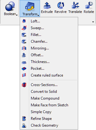
![]() - creates a face, shell or a solid shape from two or more profiles. See Loft chapter for more information.
- creates a face, shell or a solid shape from two or more profiles. See Loft chapter for more information.
![]() - creates a face, shell or a solid shape from one or more profiles, projected along a path. See Sweep chapter for more information.
- creates a face, shell or a solid shape from one or more profiles, projected along a path. See Sweep chapter for more information.
![]() - creates a fillet (round) on the selected edge(s) of an object. See Fillet chapter for more information.
- creates a fillet (round) on the selected edge(s) of an object. See Fillet chapter for more information.
![]() - chamfers the selected edge(s) of an object. See Chamfer chapter for more information.
- chamfers the selected edge(s) of an object. See Chamfer chapter for more information.
![]() - creates a reflection of the selected object. See Mirroring chapter for more information.
- creates a reflection of the selected object. See Mirroring chapter for more information.
![]() - creates copy of a selected shape at a certain distance from this shape. See Offset chapter for more information.
- creates copy of a selected shape at a certain distance from this shape. See Offset chapter for more information.
![]() - transforms selected object into a hollow object, giving to each of selected faces a defined thickness. See Thickness chapter for more information.
- transforms selected object into a hollow object, giving to each of selected faces a defined thickness. See Thickness chapter for more information.
![]() - takes a selected sketch as input and produce a pocket in the base object. See Pocket chapter for more information.
- takes a selected sketch as input and produce a pocket in the base object. See Pocket chapter for more information.
![]() - creates a ruled surface out of two edges or wires. See Ruled Surface chapter for more information.
- creates a ruled surface out of two edges or wires. See Ruled Surface chapter for more information.
![]() - creates an intersection of the selected shape with a cutting plane. See Cross-Sections chapter for more information.
- creates an intersection of the selected shape with a cutting plane. See Cross-Sections chapter for more information.
![]() - creates solid from the selected shell or compound. See Convert to Solid chapter for more information.
- creates solid from the selected shell or compound. See Convert to Solid chapter for more information.
![]() - makes a compound of selected shapes. See Make Compound chapter for more information.
- makes a compound of selected shapes. See Make Compound chapter for more information.
![]() - makes a face from selected sketches. See Make Face from Sketch chapter for more information.
- makes a face from selected sketches. See Make Face from Sketch chapter for more information.
![]() - creates simple (non-parametric) copy of the selected object(s). See Simple Copy chapter for more information.
- creates simple (non-parametric) copy of the selected object(s). See Simple Copy chapter for more information.
![]() - refines the selected object. See Refine Shape chapter for more information.
- refines the selected object. See Refine Shape chapter for more information.
![]() - analyses selected geometry for errors.
- analyses selected geometry for errors.
![]() - extends selected shape by a specified distance, in a specified direction. See Extrude chapter for more information.
- extends selected shape by a specified distance, in a specified direction. See Extrude chapter for more information.
![]() - revolves the selected object around a given axis. See Revolve chapter for more information.
- revolves the selected object around a given axis. See Revolve chapter for more information.
![]() - moves the selected geometrical objects along X, Y and Z axes. See Translate chapter for more information.
- moves the selected geometrical objects along X, Y and Z axes. See Translate chapter for more information.
![]() - rotates the selected geometrical objects. See Rotate chapter for more information.
- rotates the selected geometrical objects. See Rotate chapter for more information.
![]() - creates a clipping plane that divides the object space into two half spaces. See Clipping Plane chapter for more information.
- creates a clipping plane that divides the object space into two half spaces. See Clipping Plane chapter for more information.
![]() - measures distance between two selected points in the 3D view.
- measures distance between two selected points in the 3D view.
![]() - opens adialogue in the Task Panel for linear distance measurement.
- opens adialogue in the Task Panel for linear distance measurement.
![]() - opens adialogue in the Task Panel for angular measurement.
- opens adialogue in the Task Panel for angular measurement.
![]() - clears the linear and angular measurement.
- clears the linear and angular measurement.
![]() - shows/hides the linear and angular measurement.
- shows/hides the linear and angular measurement.
Thin Layer section

Thin Layer section contains the following commands:
![]() - defines the metal object as an infinitely thin layer. See Thin Layer chapter for more information.
- defines the metal object as an infinitely thin layer. See Thin Layer chapter for more information.
Sketcher section

Sketcher section contains the following commands:
![]() - switches to Skecher tab of QW-Modeller Ribbon
- switches to Skecher tab of QW-Modeller Ribbon
Model section
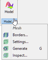
Model section contains the following commands:
![]() - switches to Model tab of QW-Modeller Ribbon
- switches to Model tab of QW-Modeller Ribbon
![]() - opens Boundary Conditions dialogue with options for project boundaries configuration. See Borders chapter for more information.
- opens Boundary Conditions dialogue with options for project boundaries configuration. See Borders chapter for more information.
![]() - opens Mesh Settings dialogue with options for FDTD mesh configuration. See Mesh Settings chapter for more information.
- opens Mesh Settings dialogue with options for FDTD mesh configuration. See Mesh Settings chapter for more information.
![]() - recalculates FDTD mesh.
- recalculates FDTD mesh.
![]() - opens Mesh Inspect dialogue with FDTD mesh information. See Mesh Inspect chapter for more information.
- opens Mesh Inspect dialogue with FDTD mesh information. See Mesh Inspect chapter for more information.
Help section
![]()
Help section contains the following command:
![]() - opens help for Geometry commands (present chapter)
- opens help for Geometry commands (present chapter)