4.2 Circuit
The ![]() button in Model tab and Parameters->Circuit... command from main menu invoke Circuit dialogue.
button in Model tab and Parameters->Circuit... command from main menu invoke Circuit dialogue.
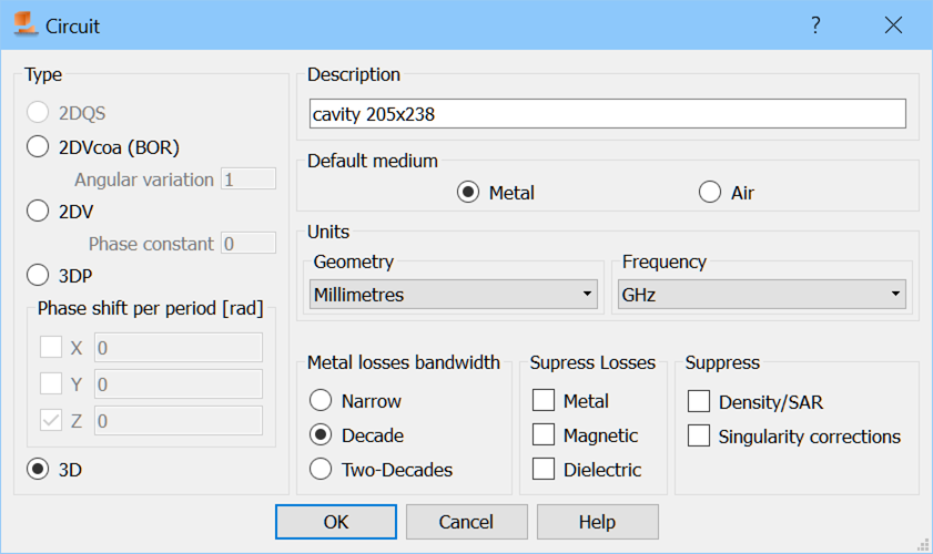
The Type frame allows determining the type of the circuit that will be analysed. In a typical application of the package as a three-dimensional tool we put 3D.
In the case of 3DP projects it is necessary to set the Periodicity direction (determine at which boundaries the periodic boundary conditions will be imposed), by checking appropriate axes and defining the Phase shifts explicitly by defining the Floquet Phase shifts per period in radians. The Floquet phase shifts can be easily calculated using the following formulae:
![]() (1)
(1)
![]() (2)
(2)
![]() (3)
(3)
where φ and θ are the spherical coordinates with Z reference axis, Li is a spatial period of the structure along i axis and c stands for the light velocity. For more information regarding periodic boundary conditions implemented in QuickWave refer to Periodic Boundary Conditions.
2DV circuit type is usable for guided problems with a known phase constant (drawn as a two-dimensional structure in XY plane).
2DVcoa (BOR) denotes axisymetrical structures - two dimensional in cylindrical coordinates (QW-V2D), also called Bodies of Revolution or BOR. In case of this type of circuits it is necessary to define proper angular variation.
The user further have a choice of the Default medium. This type of medium will be assigned to any volume in the project, which has not been explicitly defined as made of some other medium. There is a choice of two types of default media: Metal (convenient for shielded waveguide structures) or Air (which would be convenient for radiation problems).
Note the following:
The choice of the default medium is important and accidental change of it may lead to wrong simulation results. That is why the current default medium is constantly signalled in the caption of each 2D Window where we can see the expression *IN METAL* when the default medium is Metal or *IN AIR* when the default medium is Air. Moreover, the background colour of the 2D Window can be changed in 2D View Options dialogue. On the entry to a new project the default medium is Metal. Thus if the user wants to model a free space propagation (like for example in antenna applications) the default medium must change it to Air. It has been noted that a wrong default medium setting is a common user-generated error in QW-Editor operation. Thus the user should be careful with it.
Regardless of the choice of the default medium the default external boundaries of the FDTD mesh are assumed to be made of Metal, thus those are electric boundary conditions. To assign to them different properties see Special (Snapping) Planes, Symmetry Planes or Boundaries in a manual way.
Units frame allows specifying the geometry units in which the project will be created and also the frequency units. These can be specified also in the Units dialogue.
Metal Losses Bandwidth enables the choice regard the bandwidth for rigorous consideration of frequency-dependent skin effect in lossy metals. The details concerning the lossy metals model are given in the description of Metallic type of medium. In general, to reproduce the frequency dependence, we attach to each of the tangential magnetic field components an RL ladder composed of a finite number (K) of cells. With the number K increasing we can model accurately the skin effect in a wider band, but at the price of increasing computer time and memory. That is why we allow the user to make the choice of the bandwidth to be used. The three available options: Narrow, Decade and Two-Decades correspond to the number K varying from 2 to 12, with appropriate change in wide band properties of the model. The central frequency for the band is taken as: in the case of sinusoidal excitation - frequency of the source; in the case of pulse excitation - central frequency of the band of postprocessing; in the case of pulse excitation and no postprocessing - 10 GHz.
There are also five suppress options, for suppressing dielectric, metal or magnetic losses, singularity corrections, and SAR analysis. The last two options are also accessible in Export Options dialogue.