12.2 Defining elements, combined elements and materials
Let us consider ..\examples\threeel.udo presented below:
comment="example of three elements";
bitmap="threeel0.bmp";
PAR("name", oname, "3el");
PAR("length ", a, 6);
PAR("width ", b, 5);
PAR("height of first elem.", h1, 5);
PAR("height of second elem.", h2, 7);
PAR("height of third elem.", h3, 3);
PAR("shape ratio top/bottom", sr, 0.5);
PAR("medium", med, air);
ENDHEADER;
TEST( (a>0)&&(b>0)&&(h1>0)&&(h2>0)&&(h3>0), "Dimensions should be positive");
OPENOBJECT(oname);
ELEMENT(z, h1, 0, med, cubic1,IN);
NEWLINE(x-a/2, y-b/2, x+a/2, y-b/2);
ADDLINE(x+a/2,y+b/2);
ADDLINE(x-a/2,y+b/2);
CLOSELINE;
ENDELEM;
ELEMENT(z+h1,0, 5, med, prismb,INe);
NEWLINE(x-a/2, y-b/2, x+a/2, y-b/2);
ADDLINE(x+a/2,y+b/2);
ADDLINE(x-a/2,y+b/2);
CLOSELINE;
ENDELEM;
ELEMENT(z+h1+h2,0, 6, med, prismt,INe);
NEWLINE(x-sr*a/2, y-sr*b/2, x+sr*a/2, y-sr*b/2);
ADDLINE(x+sr*a/2,y+sr*b/2);
ADDLINE(x-sr*a/2,y+sr*b/2);
CLOSELINE;
ENDELEM;
ELEMENT(z+h1+h2, h3, 0, med, cubic3,INn);
NEWLINE(x-sr*a/2, y-sr*b/2, x+sr*a/2, y-sr*b/2);
ADDY(sr*b);
ADDX(-sr*a);
CLOSELINE;
ENDELEM;
CLOSEOBJ;
Please draw the above UDO in an empty project to see that it produces two cuboids connected by a prism. Thus we have three elements declared in the UDO script. Two of them are simple elements and the connecting prism is a combined element as defined in FDTD Method in QuickWave Software chapter. We will discuss here the basics of introduction of elements in UDO scripts.
· A simple element starts with a key word ELEMENT(...); and ends with a key word ENDELEM; There are six parameters to be defined in the ELEMENT(...); as specified in the Syntax of geometrical UDOs commands chapter.
· Note that first two parameters define the position of the bottom of the element and its height. The subsequent instructions are for drawing a contour of the element in XY-plane. Thus we have the commands NEWLINE(x1,x2,y1,y2); ADDLINE(x2,y2); CLOSELINE;. It is very important to close the line. Lines not closed may cause that during the meshing process the medium will “pour out” of the contour making the entire meshing incorrect. Note that if the drawn line is parallel to X or Y axis ADDLINE(x2,y2); can be replaced by simplified commands with incremental argument: ADDY(dy) or ADDX(dx). This is exemplified in the definition of the last element (cubic3) which is much simpler that the definition of the first element (cubic1).
· The consecutive points of the contour of the element must be left (counter-clockwise) oriented. Violation of this rule may result in confusion about what is placed inside the contour and what is placed outside it. Thus please be careful about that.
· The third parameter indicates the type of element. In the case of a simple element this parameter should be set to 0. In the case of a combined element we use a pair of frames: ELEMENT(...); ... ENDELEM;. The first one describes the bottom of the combined element (and its type is 5), the second describes the top of the combined element and its type is 6. Thus in the threeel.udo we have three elements but four frames ELEMENT(...); ... ENDELEM;. The first one declares the element cubic1 (name of the element is the 5-th parameter), the following two - a combined element prism (with the bottom prismb and the top prismt) and the fourth one - an element cubic3. Note that:
o Both bottom and top of combined elements have the height equal 0. The actual height of the element is defined by the difference between the levels of the bottom and the top.
o The declaration of the top must immediately follow the declaration of the bottom.
· The 4-th parameter indicates the name of the medium of which the element is made. The name of medium must be one of those used in the Media Library of the current project. The assumed parameters of the medium are those found in the Media Library unless they are overwritten in the UDO script by an instruction MEDIUMPAR(...) that gives new values of the parameters for the particular medium, as specified in the Syntax of material UDOs commands chapter.
· The 6-th parameter indicates the orientation of the contour of the element. IN indicates that declared medium (4-th parameter) is placed inside the defined left (counter-clockwise) oriented contour. This is a typical choice and practically the only one recommended to our users. Theoretically we have an option OUT placing the declared medium outside the left-oriented contour but this is an option introduced for some very special applications and not recommended for general use.
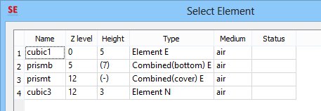
· It may be noticed that while the first element has the orientation IN the second one - orientation INe and the third one – orientation INn. Actually the declaration of IN and INe gives the same result – the top and bottom of the element enforce an E-plane of FDTD grid as defined in FDTD Method in QuickWave Software chapter (equivalent to Bottom/top kind set as Electric in Define Level dialogue) With the declaration of INn the bottom and top of the element enforce a neutral mesh snapping plane which means that there will be either E-plane or H-plane of the FDTD grid (equivalent to Bottom/top kind set as Neutral in Define Level dialogue). With the declaration of INs the bottom and top of the element enforce a suspended mesh snapping plane which does not force any mesh snapping planes; instead it is approximated with suspended mesh snapping planes The result of these declarations is visible on the list of elements presented below in the Select Element dialogue. Two first elements are marked with E and the third one with N.
Go to next Syntax of geometrical UDOs commands chapter.
Back to Syntax of the User Defined Object (UDO) language chapter.