2.12 Select Element
The ![]() button in the 2D Window toolbar and Edit->Select Element... command from 2D Window menu invoke Select Element dialogue.
button in the 2D Window toolbar and Edit->Select Element... command from 2D Window menu invoke Select Element dialogue.


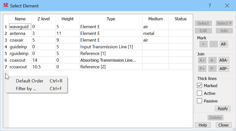
Select Element dialogue showing all elements of the project and their main characteristics. The elements can be sorted by Name, Z level, Height, Type, Medium and Status with pressing left mouse button on the header of a column. Right mouse button click on the header opens the possibility to return to unsorted Default Order (Ctrl+R) or to set Filter by… (Ctrl+F). The filtering is possible by part of Name, Z level and Hight. Unchecking the filter item(s) restores unfiltered view. An element can be selected on the list by pressing left mouse button over its line (with keyboard Shift or Ctrl to select several elements) and subjected to further operations:
Name, Zlevel, Height, Type, and Medium correspond to those set in the Define Level dialogue when drawing the element (possibly later modified via the Element Change dialogue).
Status column shows the following status information, if valid for a particular element: M - marked, A – active, P – passive, B - bi-phased, V – virtual.
If mesh control by AMIGO is on, Amigo status information is additionally shown: d - disabled, e- hard edges, h – hard (soft being a default Amigo status for elements is not shown).
For Point source/probe the following information could be shown: FD – this point is included in the FD-Probing post-processing, S – this point is included in the S-Parameters post-processing. For Lumped impedance point the type information (i.e. series, parallel etc.) will be shown.
Pressing Select button and double-clicking over an element on the list closes this dialogue and switches the 2D Window to the edit mode (indicated with square cursor ![]() ) with the following possibilities of operations:
) with the following possibilities of operations:
· To move the whole element, press left mouse button, drag the element by moving the mouse, and press left mouse button again to fix a new position of the element.
· To change a position of just one point of the element, click over the Edit-Point icon in the 2D Window toolbar, press left mouse button over the point, drag the point by moving the mouse, and press left mouse button again to fix a new position of the point.
· To edit the element, press right mouse button to enter the Element Change dialogue. It allows numerically shifting the element’s position, modifying its medium and the colour used for its display. The HV Grid button of the Element Change dialogue becomes active only for metal elements of zero height, and then can be used to convert thin metal layers to horizontal wire grids (see Wire Grids for more details). Note that invoking Edit‑Element command through the Select Element is comfortable especially when there are several elements situated in one plane very close to one another (or even interposing) and it is difficult to pick one of them up by mouse operation on the screen.
Select P(lane) command is active only when the highlighted element is a port. It changes the local 2D coordinate system of active 2D Window to the plane of the port. This is used for moving the excitation point in the transmission line port plane (refer to User Guide 3D: First insight template generation - low-order waveguide modes, User Guide 3D: Septum polariser as a six-port with higher-order waveguide modes and User Guide 3D: Monitoring of mode template generation in automatic mode chapters to see rationale for doing this).
Each of the combined elements (if present) is displayed on the list as a composition of two elements of the same name describing the lower and upper plane of the element. The types of these elements indicated on the list are bottom and cover, correspondingly. Each of them can be selected separately. However, if you move or modify bottom, cover will be moved/modified automatically in the same way. On the contrary, cover is moved and modified without influencing bottom. Cover has nominal height equal zero while bottom has nominal height equal to the actual height of the combined element (and equal to the difference in the levels of the bottom and the cover). However, remember that both these values are purely nominal, and the only way to change the height of the combined element is by changing the level of its cover.
Mark frame allows marking or unmarking higlighted element(s) using the “+”,” - ” and “All-” boxes. When an element is marked a letter M appears in its Status column. In the graphical display, marked elements will be distinguished by thick line contours (if Marked is checked in the Thick lines frame). The elements are marked to point out those, which will be subject to the subsequent Reproduce operations.
Join frame allows setting higlighted element(s) as passive or active for subsequent Join operations. During Join operations, the active elements will dominate over the passive ones in conflicting areas. For passive / active elements, a letter P / A appears in the Status column. They are also distinguished by thick line contours in the graphical display, if Active / Passive is checked in the Thick lines frame.
Thick lines frame allows deciding if marked, active or passive elements should be distinguished by thick line contours in the graphical display.
Info button opens the Element Details dialogue with the geometrical informationabout the selected element.