6.1.1 Point Source/Probe
The ![]() button in the 2D Window toolbar and Draw->I/O Ports... command from 2D Window menu invoke I/O Ports dialogue which can be used for drawing ports in a manual way.
button in the 2D Window toolbar and Draw->I/O Ports... command from 2D Window menu invoke I/O Ports dialogue which can be used for drawing ports in a manual way.
We suggest alternative and more convenient way of introducing the point source or probe port using Point/Probe dialogue.
Point Source/Probe describes a port defined by its current and voltage at certain nodes.

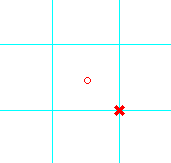
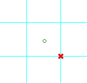
We can consider lumped point port only across one FDTD cell. The point position will be fixed by a left mouse button click or by entering the coordinates from the Keyboard Entry dialogue (after pressing K-key). Orientation is irrelevant.
It is also possible to place a point source or probe directly on the wire. This feature will be particularly convenient in the analysis of wire antennas: changes in the meshing will not need to be associated with changing the size of the gap, to keep it equal to one FDTD cell. The point source or probe port placed on the wire will “cut” a gap in the wire and work directly in that gap.
The point source or probe port can take part in the following postprocessing algorithms:
FD-Probing post-processing, which stands for frequency domain probing, and means that Fourier transforms of terminal voltage across the resistor and current through the resistor will be calculated,
S-Parameters post-processing as port No., which includes the point source or probe port in the S-Parameters extraction system together with transmission line ports (template port, modal port).
For more details refer to Point source and Point probe sections.