6.1.2 Transmission line
The ![]() button in the 2D Window toolbar and Draw->I/O Ports... command from 2D Window menu invoke I/O Ports dialogue which can be used for drawing ports in a manual way.
button in the 2D Window toolbar and Draw->I/O Ports... command from 2D Window menu invoke I/O Ports dialogue which can be used for drawing ports in a manual way.
We suggest alternative and more convenient way of introducing the transmission line port using Transmission Line Port dialogue.
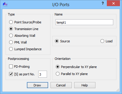
Transmission Line describes a port defined by integrals of fields over a cross-section of an arbitrary transmission line.

To excite the structure and extract any parameters at the Transmission line port we need to calculate a mode template, which is a set of transverse E and H fields of a particular mode considered for a particular frequency f in an infinite section of the transmission line (for more details refer to Template mode generation procedure).
The port can be defined as Source or Load. The declaration of the port as a source means that it will serve as the input port in the case of Sk1 element analysis, which uses excitation from one port only. To avoid confusion in the S-matrix interpretation this port should be marked as port number one (Sk1 parameters are always extracted with respect to port number one, without checking whether this is really a source). In the case of Smn analysis each port included in S-parameters extraction will serve as a source in one of the consecutive simulations.
If the Transmission line port is included in S-Parameters post-processing (via [S] as port No. option), a reference plane will be automatically generated by QW-Editor at a default distance from the port. If the [S] option is not checked, the port can serve as source or load but it will be ignored from the point of view of S-matrix analysis.
Let us also note that it is possible to define in the same place two different ports operating on two different transmission line modes (like for example vertical and horizontal polarisation in a square waveguide). In this case we define in the same place two transmission line ports and assign to each of them different mode template by a proper choice of excitation in template generation. Such a process has been exemplified in User Guide 3D: Septum polariser, User Guide 3D: First insight template generation - low-order waveguide modes and User Guide 3D: Septum polariser as a six-port with higher-order waveguide modes chapters.
Before clicking Draw, the user must specify whether the port is Perpendicular to XY plane or Parallel to XY plane, which entails that it will be drawn as a line (with the port height set in Define Level dialogue) or rectangle, respectively using mouse pointer or Keyboard Entry dialogue.
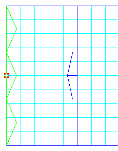
The port in XZ and YZ planes is introduced in a way similar to elements with the only difference that their base is a straight line while the elements have polygonal bases.
The port in XY planes is introduced in a similar way as a rectangular base of an element.
Line marking the Transmission Line port should be drawn parallel to one of the coordinate axis, precisely within the metal body of the i.e. waveguide. QW-Editor will not allow drawing the transmission line port obliquely. However, if you draw the port either too short or not starting precisely at the metal wall, only a part of the guide cross-section will be used for energy injection, leading to wrong simulation results. If you draw it too long, protruding into the metal wall of the guide or even further, the simulation results may be correct, but the simulation time may drastically increase if the mesh snapping properties of the port circumference imposed on the mesh snapping by the geometry produce a very small cell. This discussion underlines that if the user decides to draw a port in a manual way this operation needs to be done with special care. This is greatly simplified if one defines ports via Edit Line command or from UDO scripts.
For more details regarding transmission line ports refer to Trasmission line port excitation and Transmission line port termination.