3.5.9 Objective from file
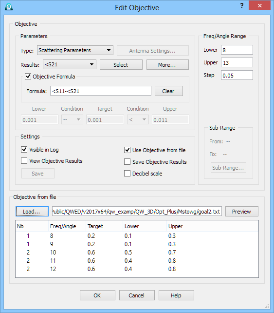
If the Use Objective from file option in the Add Objective or Edit Objective dialogue is checked, the target, lower bound and upper bound in a sub-range for a particular objective can be read from file.
Set the Parameters and Freq/Angle Range for the currently edited Objective. Select Use Objective from file, press Load... button and select a *.txt file with objective definition. Syntax of an objective file is specified in Objective file chapter. The lower part of the Add Objective or Edit Objective dialogue shows text listing of a particular objective file. The Nb column shows numbers of consecutive sub-ranges listed in the file. As specified in Objective file chapter, the number of columns must be constant for all sub-ranges listed in a file, but the sense of the third column may vary between the sub-ranges (as Lower and Upper, respectively).
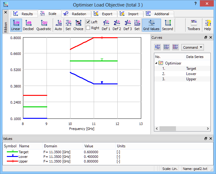
It is also possible to inspect and the objective file graphically, pressing Preview button.
QW-OptimiserPlus has a capability of importing objectives from files. One objective must be stored in one text file. Objectives defined directly in the Configure Optimiser dialogue may also be saved to such text files, for further use in other projects or for creating format templates. The format and syntax are as follows:
Symbols ! and # at the beginning of a line denote a comment line. Moreover, symbol # means the beginning of a new Sub-Range.
The actual data are listed in 2, 3 or 4 columns. The number of columns must be constant for all data in the file. The meaning of each column must be constant within each Sub-Range (and in most cases, it is constant throughout for all Sub-Ranges the file):
· The first column is always detected as consecutive points in a Sub-Range. These points will be considered as values of frequency in [GHz] for Scattering Parameters or FD Probing objectives, or as values of variable angle in [deg] for Radiation Pattern objective. The values in this column must be listed in increasing order. The first and last values in this column must coincide (within 10-6) with points of frequency / angle in the post-processing. The second column is always detected as Target.
· In the first row of values for a Sub-Range, the third column (if detected) is classified as Lower if it is smaller than Target or Upper if it is greater than Target. In consecutive rows for the same Sub-Range, it must retain the same meaning (Lower or Upper) as in the first row.
· In the first row of values for a Sub-Range, the fourth column (if detected) is classified as Lower if it is smaller than Target or Upper if it is greater than Target. In consecutive rows for the same Sub-Range, it must retain the same meaning (Lower or Upper) as in the first row.
For frequency / angle points of the post-processing in the Sub-Range, but not coincident with any point listed in the first column of the objective file, the corresponding values of Target, Upper and Lower will be calculated by linear interpolation between two neighbouring values listed in the column.
Examples:
· Target – 2 columns:
! Sub-Range Target
7.0 0.1
7.5 0.2
8.0 0.2
#New subrange – Sub-Range Target
10 0.5
11 0.7
12 0.6
· Target Lower/Upper – 3 columns: (Lower or Upper value is detected automatically)
!Sub-Range Target Upper
7 0.2 0.3
8 0.4 0.5
9 0.4 0.5
#New subrange – Sub-Range Target Lower
10 0.5 0.3
11 0.7 0.4
12 0.6 0.5
#New subrange – Sub-range Target Upper
12.3 0.1 0.2
12.5 0.2 0.3
· Target Lower Upper – 4 columns:
!Sub-Range Target Lower Upper
7 0.2 0.1 0.3
8 0.3 0.2 0.5
9 0.2 0.1 0.4
#New subrange – Sub-Range Target Lower Upper
10 0.5 0.3 0.6
11 0.7 0.4 0.8
12 0.6 0.5 0.9