2.14.3 Ferrite circulator
A stripline ferrite circulator known from the paper “FDTD analysis of microwave circulators involving saturated magnetized ferrites” proposed by J. Lenge, A. Ahland, J. Kastner, and D. Schulz is considered. It is a Y-type circulator shown in Fig. 2.14.3-1. Metal stripes are modelled as a perfect conductor.
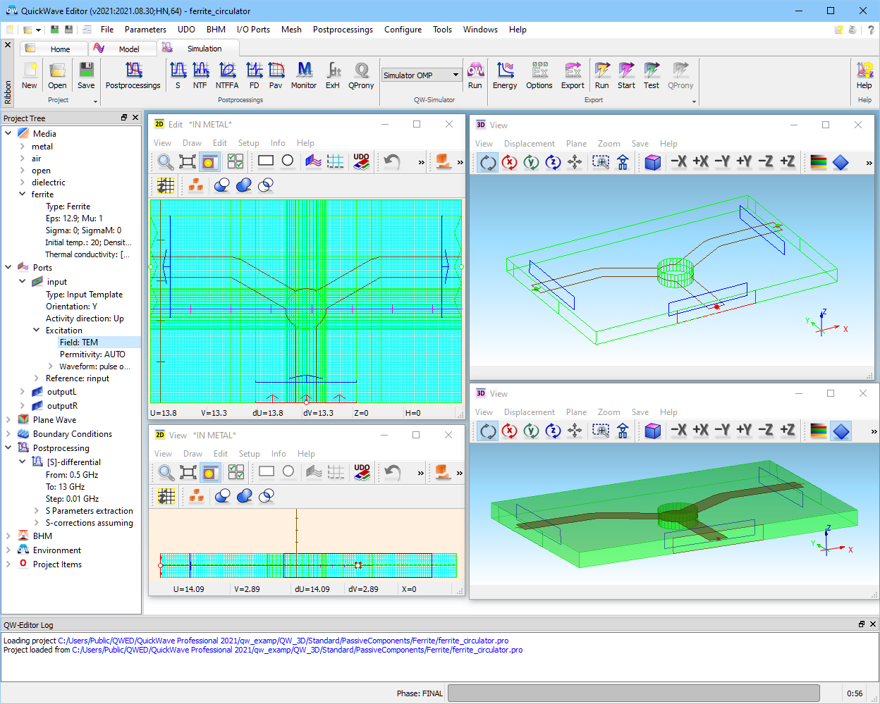
The ..\PassiveComponents\Ferrite\ferrite_circulator.pro is visualised in QW-Editor in three windows: two 2D Windows and one 3D Window. The 2D Windows (right and lower left) show the cross-sections in the XY- and XZ- planes. In the middle of the circulator two ferrite posts are situated.
Fig. 2.14.3-1 QW-Editor display of the ..Materials\Ferrite\ferrite_circulator.pro example.
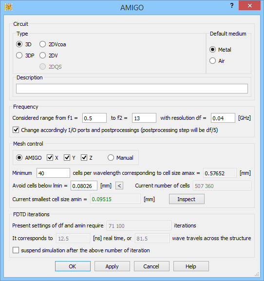
Fig. 2.14.3-2 The AMIGO dialogue window.
To mesh the structure, the AMIGO option is applied. Settings for the AMIGO are shown in Fig. 2.14.3-2.
The structure that we are considering contains two ferrite posts, thus the specific parameters of the ferrite medium need to be defined. Those parameters are defined in Project Media. Fig. 2.14.3-3 shows the parameters of ferrite material being of Ferrite. Eps, Mu, Sigma, SigmaM have the same meaning as for a dielectric medium and are permittivity, permeability, conductivity and magnetic loss, respectively. Three other parameters are specific for a ferrite material. Alpha is a dimensionless parameter which stands for magnetic losses, Ms is a saturation magnetization expressed in [T], and Hi is a static internal magnetic field expressed in [A/m]. Parameters of the ferrite medium can be also set directly by UDO commands. There are two commands, which allow setting parameters of the ferrite material. The first is MEDIUMPAR, which for the ferriate medium looks as follows:
MEDIUMPAR (medname, Eps, Mu, Sigma, SigmaM, alpha, Ms, Hi, 0, 0, 0, 0, 0, dens).
The other is a CALL type command:
CALL (“actions/newferrite.udo”, medname, Eps, Mu, Sigma, SigmaM, alpha, Ms, Hi, dens, x, y, z, 13).
In both cases, medname is a medium name, meaning of the remaining parameters has already been explained.
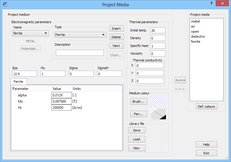
Fig. 2.14.3-3 The Project Media dialogue window for ferrite_circulator.pro.
The considered circulator has been excited with a pulse in the frequency range 0.5 - 13 GHz. Because it is a stripline circulator, the exciting field has been set to the TEM mode. The settings for the input port are shown in Fig. 2.14.3-4. Both output ports have the same settings (left output port is a port number 2, right output port is number 3).
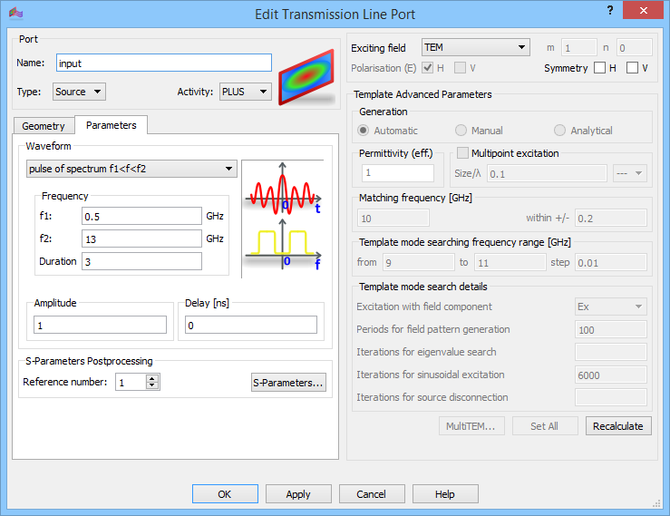
Fig. 2.14.3-4 The Edit Transmission Line Port dialogue with source port settings.
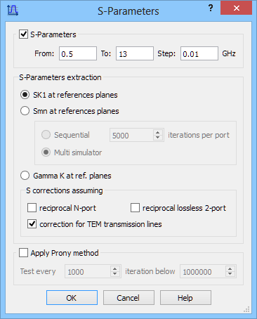
Fig. 2.14.3-5 The S-Parameters dialogue for ferrite_circulator.pro.
Fig. 2.14.3-5 shows the S-Parameters dialogue for the considered ferrite circulator. Every circuit/structure which includes magnetised ferrite elements is non-reciprocal. This is the reason why checkboxes in S-correction assuming... part are unchecked.
Fig. 2.14.3-6 and Fig. 2.14.3-7 show S-parameters obtained for the ferrite circulator. The isolation for both pass bands is about 15 dB.
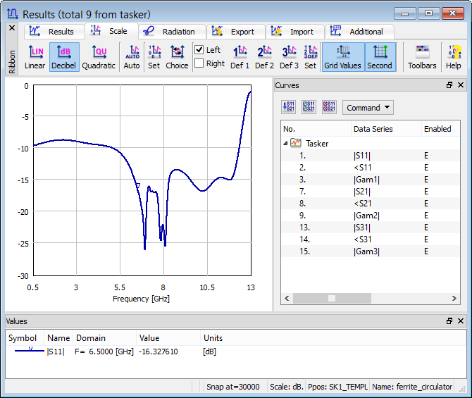
Fig. 2.14.3-6 Results of analysis of |S11| of ferrite_circulator.pro.
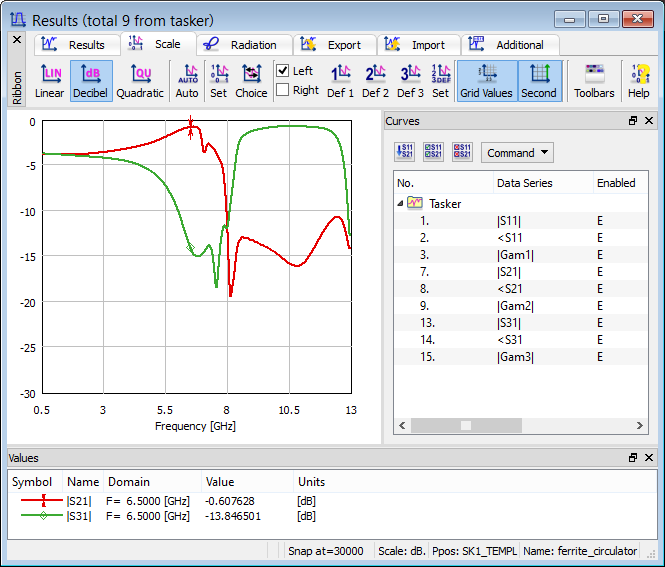
Fig. 2.14.3-7 Results of analysis of |S21| and |S31| of ferrite_circulator.pro.