2.3.10 Radiation patterns for circular polarisation
In QuickWave, except for extracting radiation patterns in linear polarisation (Etheta and Ephi curves), it is also possible to switch to circular polarisation (Eleft and Eright curves). The convention for the left-handed Eleft and right-handed Eright circular polarisation is that for the outgoing wave.
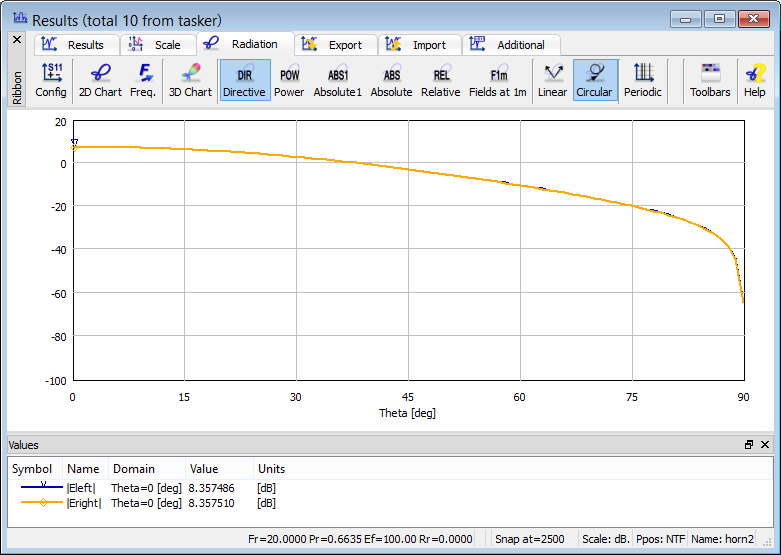
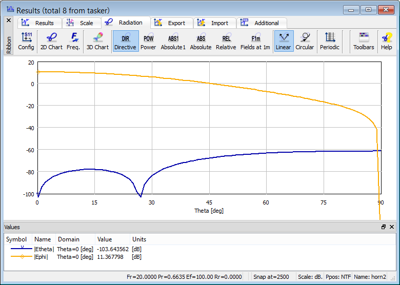
Fig. 2.3.10-1 Radiation patterns for horn2.pro example displayed in linear polarisation (upper) and circular polarisation (lower).
Consider again ..\Antennas\horns\horn2.pro example. Invoking the Results window with 2D radiation pattern results for the first time (using ![]() button in 2D Radiation Pattern section of Results tab in QW-Simulator) shows the radiation pattern as in Fig. 2.3.2-3 (Etheta in the full 0..180 deg range of theta angle), while its second invoking brings up the upper display of Fig. 2.3.10-1 – with both Ephi and Etheta curves in the 0..90 deg theta range. Pressing the button for the third time opens the display as the lower one in Fig. 2.3.10-1, which circular polarisation components. The left- and right-handed polarisation curves practically overlap since this antenna radiates in one linear polarisation only.
button in 2D Radiation Pattern section of Results tab in QW-Simulator) shows the radiation pattern as in Fig. 2.3.2-3 (Etheta in the full 0..180 deg range of theta angle), while its second invoking brings up the upper display of Fig. 2.3.10-1 – with both Ephi and Etheta curves in the 0..90 deg theta range. Pressing the button for the third time opens the display as the lower one in Fig. 2.3.10-1, which circular polarisation components. The left- and right-handed polarisation curves practically overlap since this antenna radiates in one linear polarisation only.
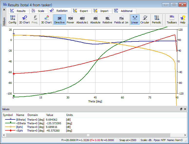
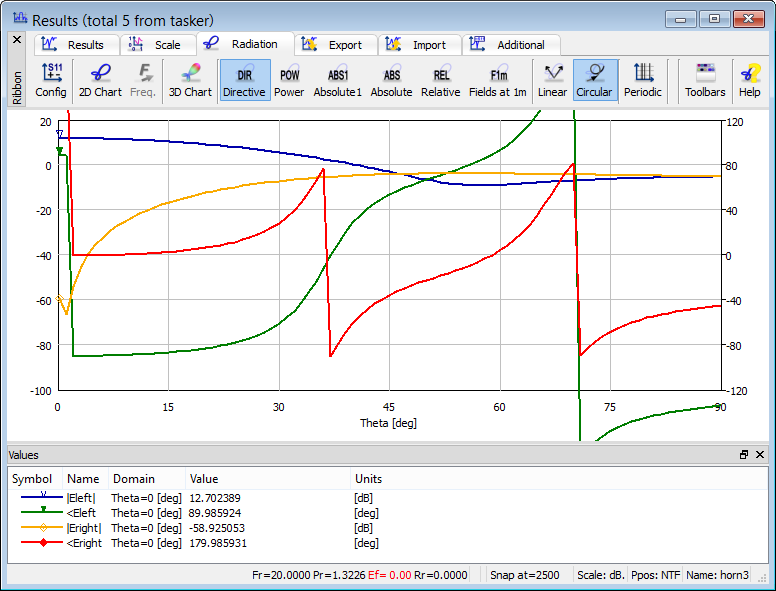
Fig. 2.3.10-2 Radiation patterns for horn3.pro example displayed in linear polarisation (upper) and circular polarisation (lower).
Now consider ..\Antennas\horns\horn3.pro example. It is similar to ..\Antennas\horns\horn2.pro, however, both feeding waveguide cross-section and horn opening are now square in shapes. The second input port is added and assigned to the TE01 mode. The TE10 and TE01 ports are fed with time-waveforms shifted by 0.0125 ns. This corresponds to a phase shift of 90 deg at 20 GHz, whereat radiation patterns will be calculated.
First invoking of the Results window with 2D radiation pattern results (using ![]() button in 2D Radiation Pattern section of Results tab in QW-Simulator) brings up the upper display of Fig. 2.3.10-2 – with amplitudes and phases of Ephi and Etheta curves in the 0..90 deg theta range. As expected, along the Z-axis (for theta=0) the Etheta and Ephi curves are equal in magnitude and phase-shifted by 90 deg. Pressing the button for the second time opens the lower display of Fig. 2.3.10-2 with circular polarisation curves. We see that the radiated signal is an almost pure circularly polarised wave Eleft, with Eright being almost 90 dB weaker. With increasing angle theta, phase difference between the two linearly polarised signals Etheta and Ephi decreases, and the two circularly polarised signals Eleft and Eright become equal around theta=45 deg.
button in 2D Radiation Pattern section of Results tab in QW-Simulator) brings up the upper display of Fig. 2.3.10-2 – with amplitudes and phases of Ephi and Etheta curves in the 0..90 deg theta range. As expected, along the Z-axis (for theta=0) the Etheta and Ephi curves are equal in magnitude and phase-shifted by 90 deg. Pressing the button for the second time opens the lower display of Fig. 2.3.10-2 with circular polarisation curves. We see that the radiated signal is an almost pure circularly polarised wave Eleft, with Eright being almost 90 dB weaker. With increasing angle theta, phase difference between the two linearly polarised signals Etheta and Ephi decreases, and the two circularly polarised signals Eleft and Eright become equal around theta=45 deg.