Home > QW-Modeller > QW-Modeller Manual > 6 FDTD Mesh > 6.2 Mesh Box
6.2 Mesh Box
Mesh Box is a simple object, which enables setting a specific meshing in the area limited by its size.
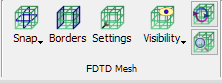
The ![]() command from the drop-dowm menu under
command from the drop-dowm menu under ![]() button in the Model tab and Mesh->Mesh Box... command from main menu invoke Create Mesh Box dialogue.
button in the Model tab and Mesh->Mesh Box... command from main menu invoke Create Mesh Box dialogue.
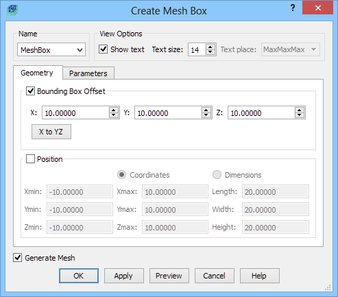
In the Geometry tab the user needs to define the dimensions of the Mesh Box. It can be done in two ways. First one is using Bounding Box Offset option, where the Mesh Box is drawn at the defined offset from the bounding box of the project structure. The offset is defined for each direction and applies to each side from the structure. For the data in a given dialogue, the Mesh Box dimension in each direction will be 20 units bigger than the bounding box of the structure in the project. Please note that if the project contains only the geometry, the bounding box is determined by this geometry. If there is a i.e. NTF Box surrounding the geometry, the bounding box is determined by the NTF Box dimensions. If the user wants to place the Mesh Box “inside” the NTF Box, the second option for defining the Mesh Box dimensions should be used.
Second solution is using Position option, where the user can choose Coordinates or Dimensions. While using Coordinates option the MinMax coordinates of the Mesh Box in each direction should be defined. For the Dimensions option, length, width, and height of the Mesh Box should be given together with the Min coordinates at which the box geometry starts.
After setting the required size of the Mesh Box the user needs to specify the mesh cell size in the box, in the Parameters tab. The mesh cell size, enforced in the Mesh Cell Size area, can be specified separately for each direction in the X, Y, Z fields. Additionally the user can decide whether the mesh cell size in a chosen direction should be modified according to the given value or the global setting (set in Mesh Settings dialogue) should be kept. To keep the global setting in a chosen direction, an appropriate checkbox should be unchecked.
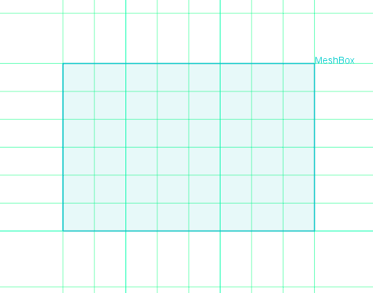
The Snap to area allow snapping mesh to the specified Mesh Box edge:
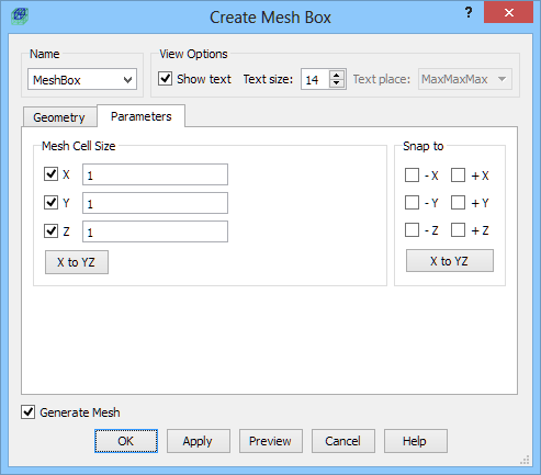

No snap to edges and snap to -X, +X, -Y, +Y edges.
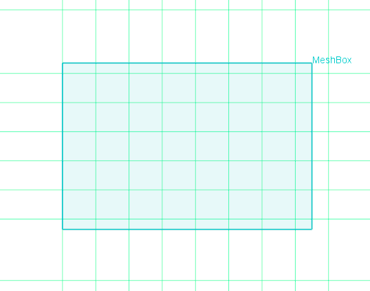
Snap to -X edge and snap to -X, +X edges.
The user can define as many Mesh Boxes as required. If Mesh Boxes overlap, the mesh cell size in the overlapping area is determined by the Mesh Box with the smallest cell size set.
Python code
The python code, which can be useful when creating project scripts, generated by Create Mesh Box dialogue for default parameters:
from FreeCAD import Base
QW_Modeller.addQWObject("QW_Modeller::MeshBox","MeshBox")
App.ActiveDocument.MeshBox.OffsetX = 10.00000
App.ActiveDocument.MeshBox.OffsetY = 10.00000
App.ActiveDocument.MeshBox.OffsetZ = 10.00000
App.ActiveDocument.MeshBox.Length = 30.00000
App.ActiveDocument.MeshBox.Width = 30.00000
App.ActiveDocument.MeshBox.Height = 30.00000
App.ActiveDocument.MeshBox.Placement = Base.Placement(Base.Vector(5.00000,5.00000,5.00000),Base.Rotation(0.00000,0.00000,0.00000,1.00000))
Gui.ActiveDocument.MeshBox.ShowText = True
Gui.ActiveDocument.MeshBox.TextSize = 14
App.ActiveDocument.MeshBox.MeshX = True
App.ActiveDocument.MeshBox.MeshY = True
App.ActiveDocument.MeshBox.MeshZ = True
App.ActiveDocument.MeshBox.MeshXCellSize = 1.00000
App.ActiveDocument.MeshBox.MeshYCellSize = 1.00000
App.ActiveDocument.MeshBox.MeshZCellSize = 1.00000
App.ActiveDocument.MeshBox.SnapToXMinus = False
App.ActiveDocument.MeshBox.SnapToXPlus = False
App.ActiveDocument.MeshBox.SnapToYMinus = False
App.ActiveDocument.MeshBox.SnapToYPlus = False
App.ActiveDocument.MeshBox.SnapToZMinus = False
App.ActiveDocument.MeshBox.SnapToZPlus = False
App.ActiveDocument.recompute()
Gui.SendMsgToActiveView("ViewFit")
See also Mesh Snapping Plane, Borders, Mesh Settings, Mesh Inspect and Mesh Visualisation chapters for more information.
Home > QW-Modeller > QW-Modeller Manual > 6 FDTD Mesh > 6.2 Mesh Box