6.6 Mesh Visualisation
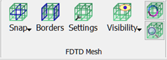
The FDTD Mesh main visualisation options are available in the drop-down menu under ![]() button in the FDTD Mesh section in the Model tab and contains the following commands:
button in the FDTD Mesh section in the Model tab and contains the following commands:
![]() - shows/hides FDTD mesh in X direction
- shows/hides FDTD mesh in X direction
![]() - shows/hides FDTD mesh in Y direction
- shows/hides FDTD mesh in Y direction
![]() - shows/hides FDTD mesh in Z direction
- shows/hides FDTD mesh in Z direction
![]() - shows/hides FDTD mesh
- shows/hides FDTD mesh
![]() - shows/hides electric FDTD mesh
- shows/hides electric FDTD mesh
![]() - shows/hides magnetic FDTD mesh
- shows/hides magnetic FDTD mesh
![]() - shows/hides FDTD mesh in a box form
- shows/hides FDTD mesh in a box form
![]() - shows/hides FDTD mesh in a short lines form
- shows/hides FDTD mesh in a short lines form
![]() - shows/hides FDTD mesh boundary conditions. See Borders chapter for more information.
- shows/hides FDTD mesh boundary conditions. See Borders chapter for more information.
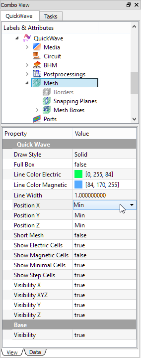
All FDTD Mesh visualisation options are available in the Mesh group property editor in the View group:

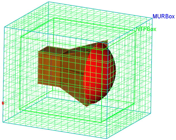
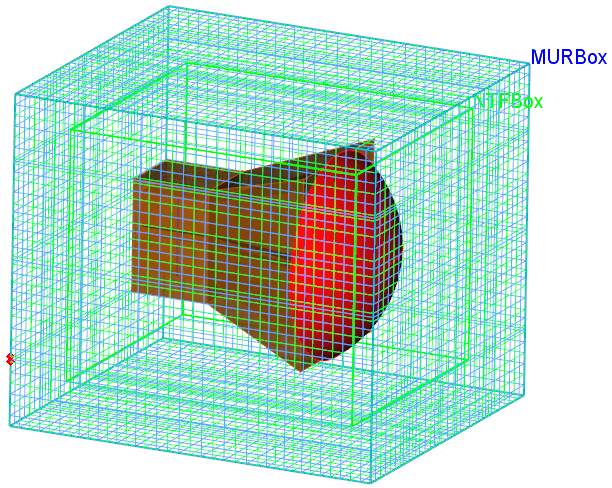
Horn antenna with dielectric lens – box with FDTD Mesh long lines with E mesh and with E and H mesh.
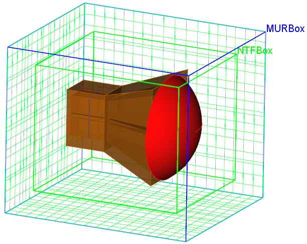
Horn antenna with dielectric lens – different positions of FDTD E Mesh long lines.


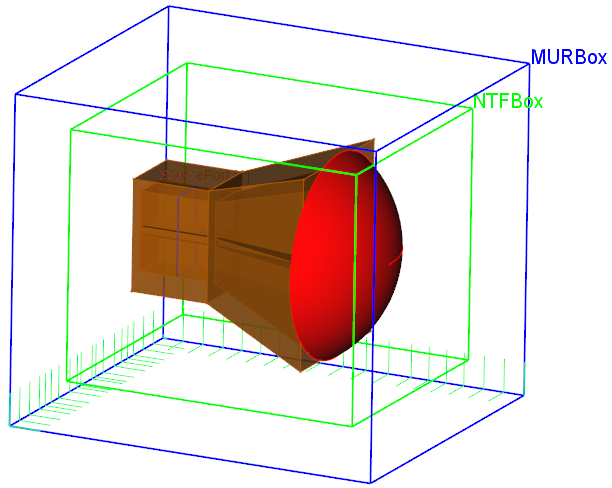
Horn antenna with dielectric lens – FDTD E and H Mesh short lines and FDTD E Mesh short lines in X and Y directions.
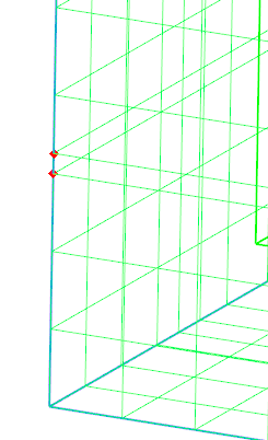
Minimal cell indicated with red dots and cell size step indicated with yellow hourglasses.
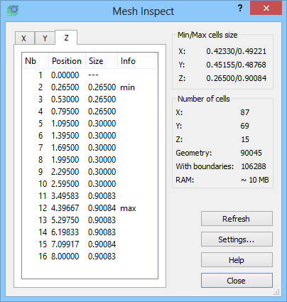
See also Mesh Snapping Plane, Mesh Box, Borders, Mesh Settings and Mesh Inspect chapters for more information.