6.4 Mesh Settings
The ![]() button in the Model tab and Mesh->Settings... command from main menu allow defining the global mesh settings in the Mesh Settings dialogue.
button in the Model tab and Mesh->Settings... command from main menu allow defining the global mesh settings in the Mesh Settings dialogue.
There are two main options for setting the global meshing: manual and automatic (Amigo). Those options are available in the Maximum Cell Size frame.
6.4.1.1 Manual Meshing
Manual meshing enforces a user defined cell size along specified axis. The user has a possibility of using Manual or Amigo meshing for each direction separately. It can be chosen by checking an appropriate checkboxes in the Manual or Amigo frames. If Manual meshing is checked for a given direction, a cell size needs to be specified. The X to YZ button copies the X cell size into the Y and Z ones.
6.4.1.2 AMIGO Meshing
Amigo enforces the mesh with a cell size specified by a given Cells per Wavelength ratio. This option takes into account the value of electric permittivity, magnetic permeability, electric conductivity and magnetic loss of the objects’ materials. If Amigo option is chosen for a particular axis, the Cells per Wavelength field, which needs to be filled, becomes active. One value of the Cells per Wavelength variable is set for all directions and a corresponding cell size (minimum from all objects’ materials) is displayed next to each axis. Frequency group allows setting the frequency band of interest. The frequency band can be set manually or taken from the project clicking Auto button.
6.4.1.3 Other Meshing Options
In the Position frame the user can set the position of the FDTD mesh visualisation when box form of FDTD mesh visualisation is off.
In the Cell Size Step frame the user can introduce maximal accepted cell size step between adjacent cells and activate automatic mesh correction in each direction.
In the Snap To frame the user can activate enforcing additional mesh snapping planes and minimal distance between them. The Metal Geometry and Non-Metal Geometry options allow enforcing mesh snapping planes at all geometry elements (vertices, edges, etc.) for metal and other materials objects, respectively. The Set button invokes Snap mesh to dialogue where the mesh snapping planes can be enforced in each direction separately by checking an appropriate checkboxes.
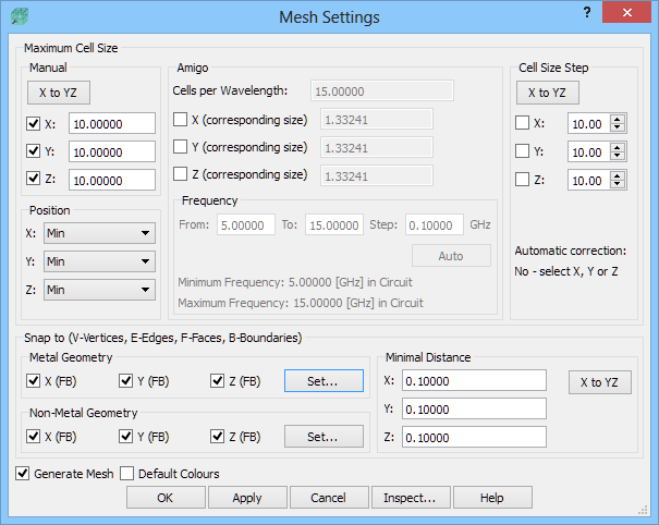
The Minimal Distance option prevents placing two automatic (resulting from Metal Geometry and Non-Metal Geometry options) mesh snapping planes in a distance smaller than the one specified in a particular direction. This distance condition is not taken into account in case of mesh snapping planes enforced by the user manually, through Snap push button.
The mesh will be automatically generated when pressing OK button if Generate mesh checkbox is checked.
Python code
The python code, which can be useful when creating project scripts, generated by Mesh Settings dialogue for default parameters:
App.ActiveDocument.QW_Mesh.CellX = 10.00000
App.ActiveDocument.QW_Mesh.CellY = 10.00000
App.ActiveDocument.QW_Mesh.CellZ = 10.00000
App.ActiveDocument.QW_Mesh.AutoSnapToGeometryX = True
App.ActiveDocument.QW_Mesh.AutoSnapToGeometryY = True
App.ActiveDocument.QW_Mesh.AutoSnapToGeometryZ = True
App.ActiveDocument.QW_Mesh.AutoSnapVertexX = False
App.ActiveDocument.QW_Mesh.AutoSnapVertexY = False
App.ActiveDocument.QW_Mesh.AutoSnapVertexZ = False
App.ActiveDocument.QW_Mesh.AutoSnapEdgeX = False
App.ActiveDocument.QW_Mesh.AutoSnapEdgeY = False
App.ActiveDocument.QW_Mesh.AutoSnapEdgeZ = False
App.ActiveDocument.QW_Mesh.AutoSnapFaceX = True
App.ActiveDocument.QW_Mesh.AutoSnapFaceY = True
App.ActiveDocument.QW_Mesh.AutoSnapFaceZ = True
App.ActiveDocument.QW_Mesh.AutoSnapFaceBoundaryX = True
App.ActiveDocument.QW_Mesh.AutoSnapFaceBoundaryY = True
App.ActiveDocument.QW_Mesh.AutoSnapFaceBoundaryZ = True
App.ActiveDocument.QW_Mesh.AutoSnapToMetalX = True
App.ActiveDocument.QW_Mesh.AutoSnapToMetalY = True
App.ActiveDocument.QW_Mesh.AutoSnapToMetalZ = True
App.ActiveDocument.QW_Mesh.AutoSnapMetalVertexX = False
App.ActiveDocument.QW_Mesh.AutoSnapMetalVertexY = False
App.ActiveDocument.QW_Mesh.AutoSnapMetalVertexZ = False
App.ActiveDocument.QW_Mesh.AutoSnapMetalEdgeX = False
App.ActiveDocument.QW_Mesh.AutoSnapMetalEdgeY = False
App.ActiveDocument.QW_Mesh.AutoSnapMetalEdgeZ = False
App.ActiveDocument.QW_Mesh.AutoSnapMetalFaceX = True
App.ActiveDocument.QW_Mesh.AutoSnapMetalFaceY = True
App.ActiveDocument.QW_Mesh.AutoSnapMetalFaceZ = True
App.ActiveDocument.QW_Mesh.AutoSnapMetalFaceBoundaryX = True
App.ActiveDocument.QW_Mesh.AutoSnapMetalFaceBoundaryY = True
App.ActiveDocument.QW_Mesh.AutoSnapMetalFaceBoundaryZ = True
App.ActiveDocument.QW_Mesh.MinCellX = 0.10000
App.ActiveDocument.QW_Mesh.MinCellY = 0.10000
App.ActiveDocument.QW_Mesh.MinCellZ = 0.10000
App.ActiveDocument.QW_Mesh.AmigoCellsPerWavelength = 15.00000
App.ActiveDocument.QW_Mesh.AmigoFrequencyMin = 5.00000
App.ActiveDocument.QW_Mesh.AmigoFrequencyMax = 15.00000
App.ActiveDocument.QW_Mesh.AmigoFrequencyStep = 0.10000
App.ActiveDocument.QW_Mesh.AmigoX = False
App.ActiveDocument.QW_Mesh.AmigoY = False
App.ActiveDocument.QW_Mesh.AmigoZ = False
App.ActiveDocument.QW_Mesh.XCellsStepRatio = 10.00000
App.ActiveDocument.QW_Mesh.YCellsStepRatio = 10.00000
App.ActiveDocument.QW_Mesh.ZCellsStepRatio = 10.00000
App.ActiveDocument.QW_Mesh.AutomaticXCellsStepCorrection = False
App.ActiveDocument.QW_Mesh.AutomaticYCellsStepCorrection = False
App.ActiveDocument.QW_Mesh.AutomaticZCellsStepCorrection = False
See also Mesh Snapping Plane, Mesh Box, Borders, Mesh Inspect and Mesh Visualisation chapters for more information.