
2.11 Two-reflector Cassegrain antenna
Radiating horns are most frequently used as feeders of reflector antennas. In A simple horn antenna a simple horn antenna has been analysed. In Application of AMIGO a more complicated corrugated horn has been considered as an application of the AMIGO meshing system. In this section, we will discuss a so called Cassegrain antenna wherein two reflectors are applied. The primary reflector is a hyperbolic one (having its focal point behind the reflecting surface). The wave reflected from the primary reflector impinges on the main parabolic reflector (having the focal point in front of the reflecting surface). Typically, the reflectors are placed in such a way that their focal points coincide, as presented in Fig. 2.11-1.

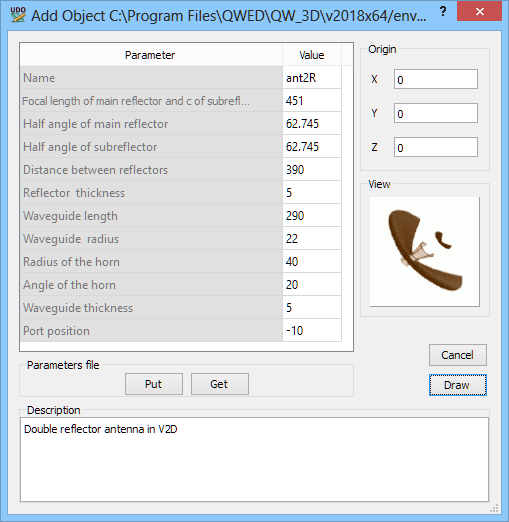
Fig. 2.11-1 A two-reflector Cassegrain antenna considered in cassant1.pro example.
Fig. 2.11-1 illustrates the parameters of elib/V2Dreflant/ant2R.udo applied in constructing Standard/Reflant/cassant1.pro.
The procedures for running simulation of axisymmetrical antennas and extracting relevant parameters have been extensively described in A simple horn antenna and Application of AMIGO. Thus they will not be repeated here. We shall only formulate several comments specific for this example.
§ The parameters of the antenna set in cassant.pro have not been optimised for the best performance. They should be treated as an illustration of the software use in the case of multi-reflector antenna structures, rather than an example of a technical solution. In particular, a very simple feeding horn is applied here, while typically corrugated horns are incorporated in Cassegrain antennas.
§ There are many conflicting requirements in this kind of structures. When a subreflector is placed close to the feed, it increases the level of input reflections. When it is far from the feed, the input reflection is lower but the subreflector must be bigger to reflect most of the energy towards the main reflector. On the other hand, too big reflector forms an obstacle in the main beam, and thus causes scattering harmful to the overall antenna radiation pattern.
It is difficult to extract the information about the reasons of non-perfect behaviour of reflector systems just from their radiation patterns. Electromagnetic field distributions in the region between the reflectors may be more instructive.
Run the example cassant1.pro, which is excited with sinusoidal waveform at 5.8 GHz. After about 6000 iterations, open 2D/3D Fields Distribution window. The window should open with the dynamic display of the Poynting vector in decibel scale. After enabling volume average envelope calculation (see description of Envelope tab or use Shift+O keyboard combination), QW-Simulator will start averaging the Poynting vector over time. After less than 100 iterations, we obtain the result as presented in Fig. 2.11-2. It can be seen that most of the energy reflected from the subreflector is correctly directed towards the main reflector, which in turn correctly directs that energy along the axis of the antenna. However, we can also see that a substantial amount of the energy radiated by the feed misses the subreflector or is scattered at its edge. This indicates that we should try and improve the interaction between the feed and the subreflector. This can be done by changing the feeding horn so that it radiates a narrower beam towards the subreflector or by changing the subreflector position or size. The user is encouraged to experiment with the example and verify how effective such changes might be.
Fig. 2.11-2 Distribution of time average of the Poynting vector in the Cassegrain antenna at 5.8 GHz.
