
4.1.1 Ribbon
2D/3D Fields Distribution window Ribbon contains of the following tabs:


For QW-3D projects the following E and H components are available:

![]() - displays Ex component of electric field
- displays Ex component of electric field
![]() - displays Ey component of electric field
- displays Ey component of electric field
![]() - displays Ez component of electric field
- displays Ez component of electric field
![]() - displays total electric field E
- displays total electric field E
![]() - displays Hx component of magnetic field
- displays Hx component of magnetic field
![]() - displays Hy component of magnetic field
- displays Hy component of magnetic field
![]() - displays Hz component of magnetic field
- displays Hz component of magnetic field
![]() - displays total magnetic field H
- displays total magnetic field H
For QW-3D projects and the quasistatic template the following E and H components are available:

![]() - displays electric potential Ue
- displays electric potential Ue
![]() - displays Dx component of electric displacement field
- displays Dx component of electric displacement field
![]() - displays Dy component of electric displacement field
- displays Dy component of electric displacement field
![]() - displays total electric displacement field D
- displays total electric displacement field D
![]() - displays magnetic potential Um
- displays magnetic potential Um
![]() - displays Hx component of magnetic field
- displays Hx component of magnetic field
![]() - displays Hy component of magnetic field
- displays Hy component of magnetic field
![]() - displays total magnetic field H
- displays total magnetic field H
For QW-V2D projects the following E and H components are available:

![]() - displays Ex component of electric field
- displays Ex component of electric field
![]() - displays Er component of electric field
- displays Er component of electric field
![]() - displays Ej component of electric field
- displays Ej component of electric field
![]() - displays total electric field E
- displays total electric field E
![]() - displays Hx component of magnetic field
- displays Hx component of magnetic field
![]() - displays Hr component of magnetic field
- displays Hr component of magnetic field
![]() - displays Hj component of magnetic field
- displays Hj component of magnetic field
![]() - displays total magnetic field H
- displays total magnetic field H
For QW-V2D projects and the quasistatic template the following E and H components are available:

![]() - displays electric potential Ue
- displays electric potential Ue
![]() - displays Dr*r product
- displays Dr*r product
![]() - displays magnetic potential Um
- displays magnetic potential Um
![]() - displays Hj*r product
- displays Hj*r product
Total electric field E and total magnetic field H components choice:
 - choice of components for calculation of total electric field E and total magnetic field H
![]() - total electric field E and total magnetic field H will be calculated from X, Y and Z field components
- total electric field E and total magnetic field H will be calculated from X, Y and Z field components
![]() - total electric field E and total magnetic field H will be calculated from X and Y field components
- total electric field E and total magnetic field H will be calculated from X and Y field components
![]() - total electric field E and total magnetic field H will be calculated from X and Z field components
- total electric field E and total magnetic field H will be calculated from X and Z field components
![]() - total electric field E and total magnetic field H will be calculated from Y and Z field components
- total electric field E and total magnetic field H will be calculated from Y and Z field components
Poynting components:
![]() - displays Poynting vector Sx component
- displays Poynting vector Sx component
![]() - displays Poynting vector Sy component
- displays Poynting vector Sy component
![]() - displays Poynting vector Sz component
- displays Poynting vector Sz component
![]() - displays total Poynting vector S
- displays total Poynting vector S
Power components:
![]() - displays power dissipated
- displays power dissipated
![]() - displays power dissipated density
- displays power dissipated density
![]() - displays power dissipated in electric losses
- displays power dissipated in electric losses
![]() - displays power dissipated in magnetic losses
- displays power dissipated in magnetic losses
SAR, Temperature, Enthalpy and Total Energy components:
![]() - displays surface current
- displays surface current
![]() - displays Specific Absorption Rate (SAR) results
- displays Specific Absorption Rate (SAR) results
![]() - displays Temperature results (available with the Basic Heating Module)
- displays Temperature results (available with the Basic Heating Module)
![]() - displays Enthalpy results (available with the Basic Heating Module)
- displays Enthalpy results (available with the Basic Heating Module)
![]() - calculates the integral of selected components in time. It is enabled for power dissipated and dissipated power density and for Poynting vector if ExH Time Integral post-processing is enabled
- calculates the integral of selected components in time. It is enabled for power dissipated and dissipated power density and for Poynting vector if ExH Time Integral post-processing is enabled
![]() - displays effective media parameters
- displays effective media parameters
 - choice of effective media parameters
![]() - adjusts the displayed fields
- adjusts the displayed fields
![]() - switches to Display tab
- switches to Display tab
![]() - switches to Structure tab
- switches to Structure tab
![]() - hides the 2D/3D Fields Distribution window Ribbon and shows all 2D/3D Fields Distribution window Toolbars
- hides the 2D/3D Fields Distribution window Ribbon and shows all 2D/3D Fields Distribution window Toolbars
![]() - opens help for Components tab commands (present chapter)
- opens help for Components tab commands (present chapter)

![]() - switches to Lines Art display
- switches to Lines Art display
![]() - switches to Filled Art display
- switches to Filled Art display
![]() - switches to Points Art display
- switches to Points Art display
![]() - switches to Postuments Art display
- switches to Postuments Art display
![]() - switches to Points display
- switches to Points display
![]() - switches to Lines display
- switches to Lines display
![]() - changes the layer of cells that is displayed by one layer up
- changes the layer of cells that is displayed by one layer up
![]() - changes the layer of cells that is displayed by one layer down
- changes the layer of cells that is displayed by one layer down
![]() - opens Go to dialogue for changing currently displayed layer
- opens Go to dialogue for changing currently displayed layer
![]() - sets XY plane for the display
- sets XY plane for the display
![]() - sets XZ plane for the display
- sets XZ plane for the display
![]() - sets YZ plane for the display
- sets YZ plane for the display
![]() - opens Cross Section Options dialogue for setting cross sections
- opens Cross Section Options dialogue for setting cross sections
![]() - shows/hides cross sections
- shows/hides cross sections
![]() - amplifies the displayed fields
- amplifies the displayed fields
![]() - adjusts the displayed fields
- adjusts the displayed fields
![]() - attenuates the displayed fields
- attenuates the displayed fields
![]() - switches between 2D fields flat plane display and 2D fields display
- switches between 2D fields flat plane display and 2D fields display
![]() - switches on/off isotropic view for the display
- switches on/off isotropic view for the display
![]() - opens Field Collection Preview dialogue for preview of loaded fields collection
- opens Field Collection Preview dialogue for preview of loaded fields collection
 - commands for scale settings for Art displays:
![]() - sets Linear scale
- sets Linear scale
![]() - sets Decibel scale
- sets Decibel scale
![]() - opens Set Scale dialogue for setting scale parameters for Art displays
- opens Set Scale dialogue for setting scale parameters for Art displays
![]() - shows/hides the units and formula that are shown at the top of the colour bar
- shows/hides the units and formula that are shown at the top of the colour bar
![]() - shows/hides the minimum and maximum values of the colour scale that are shown at the top and bottom of the colour bar
- shows/hides the minimum and maximum values of the colour scale that are shown at the top and bottom of the colour bar
![]() - opens Select Font dialogue for choosing the font for units and formula and the minimum and maximum values of the colour scale that are shown at the top and bottom of the colour bar
- opens Select Font dialogue for choosing the font for units and formula and the minimum and maximum values of the colour scale that are shown at the top and bottom of the colour bar
 - change the colour palette, including user defined palettes, for Art displays
![]() - switches to the next colour palette for Art displays
- switches to the next colour palette for Art displays
![]() - opens 2D Surface Art Display Options dialogue for setting display options for Art displays
- opens 2D Surface Art Display Options dialogue for setting display options for Art displays
![]() - opens 2D Surface Display Options dialogue for setting display options for Points and Lines display
- opens 2D Surface Display Options dialogue for setting display options for Points and Lines display
![]() - switches to Display tab
- switches to Display tab
![]() - switches to Structure tab
- switches to Structure tab
![]() - hides the 2D/3D Fields Distribution window Ribbon and shows all 2D/3D Fields Distribution window Toolbars
- hides the 2D/3D Fields Distribution window Ribbon and shows all 2D/3D Fields Distribution window Toolbars
![]() - opens help for 2D Surface tab commands (present chapter)
- opens help for 2D Surface tab commands (present chapter)

![]() - switches to Thermal Discrete display
- switches to Thermal Discrete display
![]() - switches to Thermal Continuous display
- switches to Thermal Continuous display
![]() - changes the layer of cells that is displayed by one layer up
- changes the layer of cells that is displayed by one layer up
![]() - changes the layer of cells that is displayed by one layer down
- changes the layer of cells that is displayed by one layer down
![]() - opens Go to dialogue for changing currently displayed layer
- opens Go to dialogue for changing currently displayed layer
![]() - sets XY plane for the display
- sets XY plane for the display
![]() - sets XZ plane for the display
- sets XZ plane for the display
![]() - sets YZ plane for the display
- sets YZ plane for the display
![]() - shows/hides a grid of the FDTD mesh
- shows/hides a grid of the FDTD mesh
![]() - shows the display of fields against the actual shape of the analysed structure, taking also into account boundary-conformal non-rectangular cells. Note that while QW-Simulator conducts the analysis on a conformal mesh, the default way of displaying the fields is on a simplified mesh built of rectangles. Moreover, the value of a field component assigned to the cell of index i is shown over the cell of index i, neglecting the staggered arrangement of fields around the cell. This makes the default image relatively fast, but different from the actually considered model. Activating this option has two consequences:
- shows the display of fields against the actual shape of the analysed structure, taking also into account boundary-conformal non-rectangular cells. Note that while QW-Simulator conducts the analysis on a conformal mesh, the default way of displaying the fields is on a simplified mesh built of rectangles. Moreover, the value of a field component assigned to the cell of index i is shown over the cell of index i, neglecting the staggered arrangement of fields around the cell. This makes the default image relatively fast, but different from the actually considered model. Activating this option has two consequences:
the shape of the field display becomes the same as the shape of the actually modelled structure
the value of each field component is displayed around the actual location of this component on the mesh (taking into account the staggered arrangement of the fields)
![]() - shows the display of fields against the actual shape of the analysed structure, but NOT taking into account boundary-conformal non-rectangular cells
- shows the display of fields against the actual shape of the analysed structure, but NOT taking into account boundary-conformal non-rectangular cells
![]() - causes that zero field values are always displayed in the middle colour from colour bar
- causes that zero field values are always displayed in the middle colour from colour bar
![]() - switches on/off isotropic view for the display
- switches on/off isotropic view for the display
![]() - opens XYZ dialogue for viewing exact coordinates of a particular point (at the mouse cursor position)
- opens XYZ dialogue for viewing exact coordinates of a particular point (at the mouse cursor position)
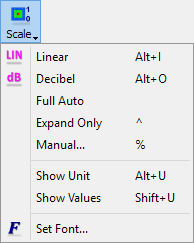 - commands for scale settings for Thermal displays:
![]() - sets Linear scale
- sets Linear scale
![]() - sets Decibel scale
- sets Decibel scale
![]() - sets scale to automatic
- sets scale to automatic
![]() - sets expand scale mode. The scale extends to distinguish the increasing (positive or negative) fields but it does not shrink.
- sets expand scale mode. The scale extends to distinguish the increasing (positive or negative) fields but it does not shrink.
![]() - opens Scaling dialogue for setting scale parameters for Thermal displays
- opens Scaling dialogue for setting scale parameters for Thermal displays
![]() - shows/hides the units and formula that are shown at the top of the colour bar
- shows/hides the units and formula that are shown at the top of the colour bar
![]() - shows/hides the minimum and maximum values of the colour scale that are shown at the top and bottom of the colour bar
- shows/hides the minimum and maximum values of the colour scale that are shown at the top and bottom of the colour bar
![]() - opens Select Font dialogue for choosing the font for units and formula and the minimum and maximum values of the colour scale that are shown at the top and bottom of the colour bar
- opens Select Font dialogue for choosing the font for units and formula and the minimum and maximum values of the colour scale that are shown at the top and bottom of the colour bar
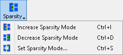 - commands for sparsity settings for Thermal Discrete display; available when Shape and Geometry options are off:
![]() - changes the space sparsity factor by one up
- changes the space sparsity factor by one up
![]() - changes the space sparsity factor by one down
- changes the space sparsity factor by one down
![]() - opens Sparse Mode dialogue for setting space sparsity factor
- opens Sparse Mode dialogue for setting space sparsity factor
 - change the colour palette, including user defined palettes, for Thermal displays
![]() - switches to the next colour palette for Thermal displays
- switches to the next colour palette for Thermal displays
![]() - opens 2D Thermal Display Options dialogue for setting display options for Thermal displays
- opens 2D Thermal Display Options dialogue for setting display options for Thermal displays
![]() - hides the 2D/3D Fields Distribution window Ribbon and shows all 2D/3D Fields Distribution window Toolbars
- hides the 2D/3D Fields Distribution window Ribbon and shows all 2D/3D Fields Distribution window Toolbars
![]() - opens help for 2D Thermal tab commands (present chapter)
- opens help for 2D Thermal tab commands (present chapter)

![]() - switches to 3D Vector display
- switches to 3D Vector display
![]() - displays total electric field E
- displays total electric field E
![]() - displays total magnetic field H
- displays total magnetic field H
![]() - displays total Poynting vector S
- displays total Poynting vector S
 - choice of components for calculation of total electric field E and total magnetic field H:
![]() - total electric field E and total magnetic field H will be calculated from X, Y and Z field components
- total electric field E and total magnetic field H will be calculated from X, Y and Z field components
![]() - total electric field E and total magnetic field H will be calculated from X and Y field components
- total electric field E and total magnetic field H will be calculated from X and Y field components
![]() - total electric field E and total magnetic field H will be calculated from X and Z field components
- total electric field E and total magnetic field H will be calculated from X and Z field components
![]() - total electric field E and total magnetic field H will be calculated from Y and Z field components
- total electric field E and total magnetic field H will be calculated from Y and Z field components
![]() - enables simultaneous viewing of total electric field E and total magnetic field H
- enables simultaneous viewing of total electric field E and total magnetic field H
![]() - detects time-average vector built of time-average components of momentary Poynting vector in each cell of the whole computational domain. This mode of display is signalled by /Avr S in the 2D/3D Fields Distribution window title bar.
- detects time-average vector built of time-average components of momentary Poynting vector in each cell of the whole computational domain. This mode of display is signalled by /Avr S in the 2D/3D Fields Distribution window title bar.
![]() - amplifies the displayed fields
- amplifies the displayed fields
![]() - adjusts the displayed fields
- adjusts the displayed fields
![]() - attenuates the displayed fields
- attenuates the displayed fields
![]() - switches between 2D fields flat plane display and volume fields display
- switches between 2D fields flat plane display and volume fields display
![]() - changes the layer of cells that is displayed by one layer up
- changes the layer of cells that is displayed by one layer up
![]() - changes the layer of cells that is displayed by one layer down
- changes the layer of cells that is displayed by one layer down
![]() - opens Go to dialogue for changing currently displayed layer
- opens Go to dialogue for changing currently displayed layer
 - commands for scale settings for 3D Vector display:
![]() - sets Linear scale
- sets Linear scale
![]() - sets Decibel scale
- sets Decibel scale
![]() - opens Set Scale dialogue for setting scale parameters for 3D Vector display
- opens Set Scale dialogue for setting scale parameters for 3D Vector display
![]() - shows/hides the units and formula that are shown at the top of the colour bar
- shows/hides the units and formula that are shown at the top of the colour bar
![]() - shows/hides the minimum and maximum values of the colour scale that are shown at the top and bottom of the colour bar
- shows/hides the minimum and maximum values of the colour scale that are shown at the top and bottom of the colour bar
![]() - opens Select Font dialogue for choosing the font for units and formula and the minimum and maximum values of the colour scale that are shown at the top and bottom of the colour bar
- opens Select Font dialogue for choosing the font for units and formula and the minimum and maximum values of the colour scale that are shown at the top and bottom of the colour bar
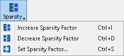 - commands for volume sparsity settings for 3D Vector display:
![]() - changes the volume sparsity factor by one up
- changes the volume sparsity factor by one up
![]() - changes the volume sparsity factor by one down
- changes the volume sparsity factor by one down
![]() - opens Sparse Factor dialogue for setting volume sparsity factor
- opens Sparse Factor dialogue for setting volume sparsity factor
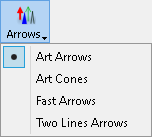 - choice of arrows type
![]() - opens 3D Vector Options dialogue for setting arrows display preferences
- opens 3D Vector Options dialogue for setting arrows display preferences
 - change the colour palette, including user defined palettes, for 3D Vector display
![]() - switches to the next colour palette for 3D Vector display
- switches to the next colour palette for 3D Vector display
![]() - switches to Display tab
- switches to Display tab
![]() - switches to Structure tab
- switches to Structure tab
![]() - hides the 2D/3D Fields Distribution window Ribbon and shows all 2D/3D Fields Distribution window Toolbars
- hides the 2D/3D Fields Distribution window Ribbon and shows all 2D/3D Fields Distribution window Toolbars
![]() - opens help for 3D Vector tab commands (present chapter)
- opens help for 3D Vector tab commands (present chapter)

![]() - switches to 3D Viewer display
- switches to 3D Viewer display
![]() - switches on/off isotropic view for the display
- switches on/off isotropic view for the display
![]() - opens 3D Viewer Settings dialogue for changing display options for 3D Viewer display
- opens 3D Viewer Settings dialogue for changing display options for 3D Viewer display
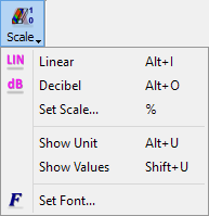 - commands for scale settings for 3D Viewer display:
![]() - sets Linear scale
- sets Linear scale
![]() - sets Decibel scale
- sets Decibel scale
![]() - opens Set Scale dialogue for setting scale parameters for 3D Viewer display
- opens Set Scale dialogue for setting scale parameters for 3D Viewer display
![]() - shows/hides the units and formula that are shown at the top of the colour bar
- shows/hides the units and formula that are shown at the top of the colour bar
![]() - shows/hides the minimum and maximum values of the colour scale that are shown at the top and bottom of the colour bar
- shows/hides the minimum and maximum values of the colour scale that are shown at the top and bottom of the colour bar
![]() - opens Select Font dialogue for choosing the font for units and formula and the minimum and maximum values of the colour scale that are shown at the top and bottom of the colour bar
- opens Select Font dialogue for choosing the font for units and formula and the minimum and maximum values of the colour scale that are shown at the top and bottom of the colour bar
 - change the colour palette, including user defined palettes, for 3D Viewer display
![]() - switches to the next colour palette for 3D Viewer display
- switches to the next colour palette for 3D Viewer display
![]() - switches to Display tab
- switches to Display tab
![]() - switches to Structure tab
- switches to Structure tab
![]() - hides the 2D/3D Fields Distribution window Ribbon and shows all 2D/3D Fields Distribution window Toolbars
- hides the 2D/3D Fields Distribution window Ribbon and shows all 2D/3D Fields Distribution window Toolbars
![]() - opens help for 3D Viewer tab commands (present chapter)
- opens help for 3D Viewer tab commands (present chapter)

![]() - switches back to tab from which current tab was switched to. It can change to the following buttons:
- switches back to tab from which current tab was switched to. It can change to the following buttons: ![]() ,
, ![]() ,
, ![]() ,
, ![]() ,
, ![]() ,
, ![]() or
or ![]() .
.
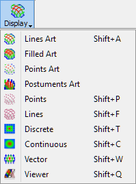 - change the display view:
![]() - switches to Lines Art display
- switches to Lines Art display
![]() - switches to Filled Art display
- switches to Filled Art display
![]() - switches to Points Art display
- switches to Points Art display
![]() - switches to Postuments Art display
- switches to Postuments Art display
![]() - switches to Points display
- switches to Points display
![]() - switches to Lines display
- switches to Lines display
![]() - switches to Thermal Discrete display
- switches to Thermal Discrete display
![]() - switches to Thermal Continuous display
- switches to Thermal Continuous display
![]() - switches to 3D Vector display
- switches to 3D Vector display
![]() - switches to 3D Viewer display
- switches to 3D Viewer display
![]() - enables free display rotation
- enables free display rotation
![]() - enables display rotation around X axis
- enables display rotation around X axis
![]() - enables display rotation around Y axis
- enables display rotation around Y axis
![]() - enables display rotation around Z axis
- enables display rotation around Z axis
![]() - enables display translation
- enables display translation
![]() - zoom the display to the selected content
- zoom the display to the selected content
![]() - zoom with the left mouse button and up and down mouse move
- zoom with the left mouse button and up and down mouse move
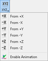 - change display to view from selected direction and enable display animation during changing the view
![]() - switches between 2D fields flat plane display and volume fields display
- switches between 2D fields flat plane display and volume fields display
![]() - sets XY plane for the display
- sets XY plane for the display
![]() - sets XZ plane for the display
- sets XZ plane for the display
![]() - sets YZ plane for the display
- sets YZ plane for the display
![]() - opens Volume Limit dialogue for defining a sub-volume of the computational domain that will be displayed
- opens Volume Limit dialogue for defining a sub-volume of the computational domain that will be displayed
![]() - opens V2D Plane Settings dialogue for setting plane for V2D projects display
- opens V2D Plane Settings dialogue for setting plane for V2D projects display
![]() - switches on/off isotropic view for the display
- switches on/off isotropic view for the display
![]() - enables light illumination of the display
- enables light illumination of the display
![]() - resets display to the default view
- resets display to the default view
![]() - opens Background Colour dialogue for setting the background solid colour or background gradient colours of the current display
- opens Background Colour dialogue for setting the background solid colour or background gradient colours of the current display
![]() - switches frozen scale on or off (Auto). In this mode the scale covered by the colour palette dynamically adjusts to the current range of the displayed field. An indication of this mode are flickering maximum and minimum field values assigned to the bottom and top of the colour bar. In some cases, the user may wish to freeze the current scale and have the shrinking or increasing field values automatically reflected in the changing range of colours used in the display.
- switches frozen scale on or off (Auto). In this mode the scale covered by the colour palette dynamically adjusts to the current range of the displayed field. An indication of this mode are flickering maximum and minimum field values assigned to the bottom and top of the colour bar. In some cases, the user may wish to freeze the current scale and have the shrinking or increasing field values automatically reflected in the changing range of colours used in the display.
![]() - switches on/off window dynamic refresh. This mode of display is signalled by /DYN in the 2D/3D Fields Distribution window title bar.
- switches on/off window dynamic refresh. This mode of display is signalled by /DYN in the 2D/3D Fields Distribution window title bar.
![]() - opens Refresh Settings dialogue with window refresh settings
- opens Refresh Settings dialogue with window refresh settings
![]() - switches to Structure tab
- switches to Structure tab
![]() - hides the 2D/3D Fields Distribution window Ribbon and shows all 2D/3D Fields Distribution window Toolbars
- hides the 2D/3D Fields Distribution window Ribbon and shows all 2D/3D Fields Distribution window Toolbars
![]() - opens help for Display tab commands (present chapter)
- opens help for Display tab commands (present chapter)

![]() - switches back to tab from which current tab was switched to. It can change to the following buttons:
- switches back to tab from which current tab was switched to. It can change to the following buttons: ![]() ,
, ![]() ,
, ![]() ,
, ![]() ,
, ![]() ,
, ![]() or
or ![]() .
.
![]() - shows/hides project structure display
- shows/hides project structure display
![]() - loads project structure
- loads project structure
![]() - switches on/off solid project structure display
- switches on/off solid project structure display
![]() - switches on/off wire project structure display
- switches on/off wire project structure display
![]() - shows/hides all non-geometrical simulation objects like, e.g. transmission line ports, ABC wall/box, NTF box, Field Monitors etc.
- shows/hides all non-geometrical simulation objects like, e.g. transmission line ports, ABC wall/box, NTF box, Field Monitors etc.
![]() - opens Structure Line Width dialogue for setting the structure line width for Art displays
- opens Structure Line Width dialogue for setting the structure line width for Art displays
![]() - opens Blend dialogue for translucency effects for solid project structure display
- opens Blend dialogue for translucency effects for solid project structure display
![]() - enables light illumination of the display
- enables light illumination of the display
![]() - displays the structure in a next view (useful for projects exported from QW-AddIn for Autodesk® Inventor® Software or QW-Modeller). See Preferences chapter for more information.
- displays the structure in a next view (useful for projects exported from QW-AddIn for Autodesk® Inventor® Software or QW-Modeller). See Preferences chapter for more information.
![]() - displays the structure in a previous view (useful for projects exported from QW-AddIn for Autodesk® Inventor® Software or QW-Modeller). See Preferences chapter for more information.
- displays the structure in a previous view (useful for projects exported from QW-AddIn for Autodesk® Inventor® Software or QW-Modeller). See Preferences chapter for more information.
![]() - controls how switching the display plane influences the display. When it is on, switching between planes (XY, XZ, YZ) shows corresponding field display keeping the structure (geometry) orientation constant.
- controls how switching the display plane influences the display. When it is on, switching between planes (XY, XZ, YZ) shows corresponding field display keeping the structure (geometry) orientation constant.
![]() - controls how switching the display plane influences the display. When this option is on, switching between planes (XY, XZ, YZ) causes that the geometry is rotated, so that orientation of the field display is maintained.
- controls how switching the display plane influences the display. When this option is on, switching between planes (XY, XZ, YZ) causes that the geometry is rotated, so that orientation of the field display is maintained.
![]() - opens BoR (V2D) View Options dialogue for 3D display of the axisymmetrical project structure
- opens BoR (V2D) View Options dialogue for 3D display of the axisymmetrical project structure
![]() - switches to Display tab
- switches to Display tab
![]() - hides the 2D/3D Fields Distribution window Ribbon and shows all 2D/3D Fields Distribution window Toolbars
- hides the 2D/3D Fields Distribution window Ribbon and shows all 2D/3D Fields Distribution window Toolbars
![]() - opens help for Structure tab commands (present chapter)
- opens help for Structure tab commands (present chapter)

![]() - turns on/off Plane Envelope Max calculation
- turns on/off Plane Envelope Max calculation
![]() - turns on/off Plane Envelope Avr calculation
- turns on/off Plane Envelope Avr calculation
![]() - turns on/off Plane Envelope DC calculation
- turns on/off Plane Envelope DC calculation
![]() - turns on/off Plane Envelope Heat calculation
- turns on/off Plane Envelope Heat calculation
![]() - turns on/off Volume Envelope Max calculation
- turns on/off Volume Envelope Max calculation
![]() - turns on/off Volume Envelope Avr calculation
- turns on/off Volume Envelope Avr calculation
![]() - turns on/off Volume Envelope Max EH Comp calculation
- turns on/off Volume Envelope Max EH Comp calculation
![]() - turns on/off Volume Envelope Avr EH Comp calculation
- turns on/off Volume Envelope Avr EH Comp calculation
![]() - turns on/off Volume Envelope Avr S calculation.
- turns on/off Volume Envelope Avr S calculation.
![]() - opens Volume Limit dialogue for defining a sub-volume of the computational domain that will be displayed
- opens Volume Limit dialogue for defining a sub-volume of the computational domain that will be displayed
![]() - amplifies the displayed fields
- amplifies the displayed fields
![]() - adjusts the displayed fields
- adjusts the displayed fields
![]() - attenuates the displayed fields
- attenuates the displayed fields
![]() - switches between 2D fields flat plane display and 2D fields display
- switches between 2D fields flat plane display and 2D fields display
![]() - saves plane instantaneous or plane envelope of the currently displayed component, in the current layer of the circuit, to a text file
- saves plane instantaneous or plane envelope of the currently displayed component, in the current layer of the circuit, to a text file
![]() - saves volume instantaneous or volume envelope of the currently displayed component over the user-defined sub-volume of the computational domain set in the appearing Volume Export Settings dialogue
- saves volume instantaneous or volume envelope of the currently displayed component over the user-defined sub-volume of the computational domain set in the appearing Volume Export Settings dialogue
![]() - switches to Display tab
- switches to Display tab
![]() - switches to Structure tab
- switches to Structure tab
![]() - hides the 2D/3D Fields Distribution window Ribbon and shows all 2D/3D Fields Distribution window Toolbars
- hides the 2D/3D Fields Distribution window Ribbon and shows all 2D/3D Fields Distribution window Toolbars
![]() - opens help for Envelope tab commands (present chapter)
- opens help for Envelope tab commands (present chapter)

![]() - saves the values of all six field components in all layers to a text file
- saves the values of all six field components in all layers to a text file
![]() - saves plane instantaneous or plane envelope of the currently displayed component, in the current layer of the circuit, to a text file
- saves plane instantaneous or plane envelope of the currently displayed component, in the current layer of the circuit, to a text file
![]() - saves plane instantaneous or plane envelope of the currently displayed component, in the current layer of the circuit, to a CSV text file
- saves plane instantaneous or plane envelope of the currently displayed component, in the current layer of the circuit, to a CSV text file
![]() - saves volume instantaneous or volume envelope of the currently displayed component over the user-defined sub-volume of the computational domain set in the appearing Volume Export Settings dialogue
- saves volume instantaneous or volume envelope of the currently displayed component over the user-defined sub-volume of the computational domain set in the appearing Volume Export Settings dialogue
![]() - saves the current display to the *.bmp, *.jpg or *.png file
- saves the current display to the *.bmp, *.jpg or *.png file
![]() - copies the current display to the Clipboard
- copies the current display to the Clipboard
![]() - exports the current display to the *.bmp file
- exports the current display to the *.bmp file
![]() - exports the current display to the *.jpg file
- exports the current display to the *.jpg file
![]() - exports the current display to the *.png file
- exports the current display to the *.png file
![]() - switches to Display tab
- switches to Display tab
![]() - switches to Structure tab
- switches to Structure tab
![]() - hides the 2D/3D Fields Distribution window Ribbon and shows all 2D/3D Fields Distribution window Toolbars
- hides the 2D/3D Fields Distribution window Ribbon and shows all 2D/3D Fields Distribution window Toolbars
![]() - opens help for Export tab commands (present chapter)
- opens help for Export tab commands (present chapter)